
Excertos do catálogo

Introduction to the HDL Wireless System
Abrir o catálogo na página 1
Wireless System
Abrir o catálogo na página 2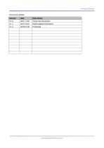
Wireless System Document update: Version Reformulated information
Abrir o catálogo na página 3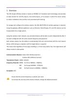
Wireless System 1. Overview The HDL Buspro Wireless System is based on IEEE802.15.4 standard mesh technology, and provides an ideal solution for retrofit projects, new build projects, or for projects in which the owner wishes to reduce installation time and the costs associated with rewiring. To manage and configure the wireless system, the HDL-MCIP-RF02.10 wireless gateway is required. Using the gateway, different platforms such as Ethernet, Wired Buspro, RF, and HDL devices can be incorporated into a single system. Using the wireless mesh network, any connected device will be able to work...
Abrir o catálogo na página 4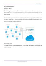
Wireless System 2. Wireless System 2.1 Mesh Mode The wireless gateway can be configured to work in mesh mode, in mesh mode each connected device will function as a signal repeater. This increases both the data transmission reliability, and the signal integrity. Since the wireless gateway has a Buspro interface, a hybrid solution using a Wireless + Wired system can also be created. This is recommended if the project has an existing Buspro system, which a user wishes to incorporate into their new system. 2.2 Bridge Mode The bridge mode can be used as an alternative to an Ethernet cable,...
Abrir o catálogo na página 5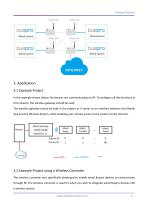
Wireless System 3. Application 3.1 Example Project In the example shown below, the devices are communicating via RF. To configure all the functions in this network, the wireless gateway should be used. The wireless gateway should be kept in the project as it serves as an interface between the Mobile App and the Wireless System, while enabling user remote access to the system via the internet. 3.2 Example Project using a Wireless Converter The wireless converter was specifically developed to enable wired Buspro devices to communicate through RF. The wireless converter is used for when you...
Abrir o catálogo na página 6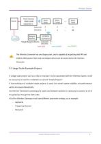
Wireless System The Wireless Converter has one Buspro port, and is capable of outputting both RF and 100mA 24DC power. Note only one Buspro device can be connected to the Wireless Converter. 3.3 Large Scale Example Project If a large scale project such as a villa or mansion is to be automated with the Wireless System, it will be necessary to treat the installation as several “Simple Projects”. If the technique of multiple simple projects is used, the overall system stability and performance will be increased dramatically. An Ethernet framework consisting of a router and network switches is...
Abrir o catálogo na página 7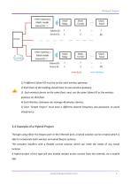
Wireless System 1) A different Subnet ID must be set for each wireless gateway. 2) Each floor of the building should have its own wireless gateway. 3) Each wireless device on the same floor, must use the same Subnet ID as the wireless gateway on that floor. 4) Each Wireless Gateway can manage 48 wireless devices. 5) Each "Simple Project" must have a different channel frequency and password, to avoid interference. 3.4 Example of a Hybrid Project Through using either the Buspro port or the Ethernet port, a hybrid solution can be created which is able to incorporate both wireless and wired...
Abrir o catálogo na página 8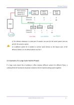
Wireless System 1) The Wireless Gateway is a dual port IP module, one port for the wired system and one port for the wireless system. 2) A different subnet ID is needed to connect wired devices to the Buspro port. If the Wireless Subnet is X, the Wired Subnet must be Y. 3.5 Example of a Large Scale Hybrid Project If a large scale project like a building or office employs different systems for different floors, a unifying Ethernet framework should be created to link the hybrid building system together.
Abrir o catálogo na página 9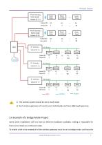
Wireless System 1) The wireless system should be set to mesh mode. 2) Each wireless gateway will need to work individually, and have differing frequencies. 3.6 Example of a Bridge Mode Project Some wired installations will not have an Ethernet backbone available, making it impossible for them to be linked via an Ethernet cable. To enable a link to be created all of the wireless gateways must be set to bridge mode, and have the www.hdlautomation.com
Abrir o catálogo na página 10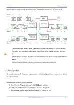
Wireless System same frequency and password. When this is done the wireless gateways will be linked via RF. 1) When the bridge mode is active, the wireless gateway can manage 24 wireless devices. 2) Wireless Gateways which are linked by Bridge Mode communicate with each other via RF. 3) Each Wireless Gateway must have an independent Subnet ID to manage its own Wireless devices. 4) Each of the Wired Buspro devices must have an independent Subnet ID. 4. Configuration The wireless gateway RF frequency and password must be configured before any wireless devices are connected to it. To...
Abrir o catálogo na página 11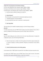
Wireless System 2) Select the correct Frequency for the Wireless Gateway For China, select WPAN band, with a frequency range of 780MHz -786MHz For Europe, select SRD band, with a frequency range of 864MHz - 870MHz For North America, select ISM band, with a frequency range of 904MHz - 928MHz Each floor requires a different frequency and subnet ID 2) Unique Password The entire project can be protected from tampering by applying a password. It is recommended that each client is issued with a unique password. 3) Enter Setup Mode The setup mode can be enabled or disabled manually, or via the...
Abrir o catálogo na página 12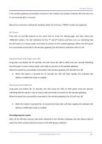
Wireless System If the wireless gateway successfully connects to the module, the wireless modules LED will return to its normal state after 5 seconds. Below the connection method for modules which do not have a “PROG” button are explained. DLP Panel: Press the 1st and 8th buttons at the same time to enter the setting page, and then select the ‘WIRELESS’ option. The LED indication for the 7th and 8th buttons will then turn on, indicating that the DLP panel is in setup mode, and ready to connect to the wireless gateway. When the DLP panel has successfully connected to the wireless gateway,...
Abrir o catálogo na página 13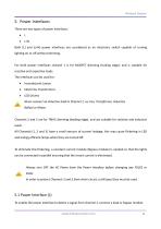
Wireless System 5. Power Interfaces There are two types of power Interfaces: Both (L) and (L+N) power interfaces are considered as an electronic switch capable of turning lighting on or off without dimming. For both power interfaces channel 1 is for MOSFET dimming (trailing edge), and is suitable for resistive and capacitive loads. The interfaces can be used for: Incandescent Lamps Electronic Transformers LED Drivers Never connect an inductive load to Channel 1, ex: Fan, Transformer, Inductive Ballast or Motor. Channels 2 and 3 are for TRIAC dimming (leading edge), and are suitable for...
Abrir o catálogo na página 14Todos os catálogos e folhetos técnicos da HDL Automation Co.
-
 S10
S109 Páginas
-
 Tile
Tile4 Páginas
-
 Granite Display
9 Páginas
-
 Blind Motor
4 Páginas
-
 Curtain Motor
9 Páginas
-
 KNX 17&19
2 Páginas
-
 HDL Museum Project Reference
14 Páginas
-
 HDL GraView Platform
10 Páginas
-
 HDL Demo Cases
16 Páginas
-
 Tile Series Control Panel
64 Páginas
-
 HDL Demo Cases-Control Panels
14 Páginas
-
 HDL Eco Solutions
28 Páginas
-
 HDL Lighting
36 Páginas
-
 Tile Display
8 Páginas
-
 HDL Intercom Solutions
28 Páginas
-
 HDL Smart Lighting Solution
45 Páginas
-
 Source 7
12 Páginas
-
 INTELLIGENT CONTROL PANELS
16 Páginas
-
 HDL Product Catalogue
83 Páginas
-
 HDL SMART SOLUTIONS
56 Páginas
-
 SMART HOTEL PROJECTS
48 Páginas
-
 COMPANY PROFILE
9 Páginas
-
 HDL Residential Solutions
34 Páginas

