Excertos do catálogo
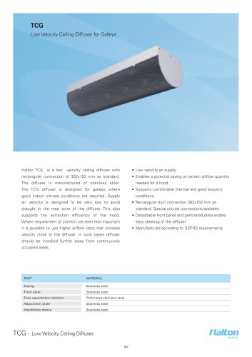
ULE Supply air valve for wall installation Supply air valve for wall installation with adjustable operations Flow pattern selection and pressure loss adjustment by front plate Airflow rate measurement and adjustment facility Detacable front plate
Abrir o catálogo na página 1
PART MATERIAL NOTE Collar Steel Front plate Steel Gasket Rubber combound Painted Finishing Special colour available White RAL 9010
Abrir o catálogo na página 3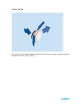
The supply air flow is directed slightly towards the ceiling. The throw length is adjusted by turning the adjustment screw open or closed.
Abrir o catálogo na página 4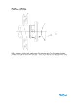
ULE is installed to the duct with finger screws from inside the valve. The front plate is mounted and the correct adjustment position selected. A plastic plug is fitted to cover the adjustment screw.
Abrir o catálogo na página 5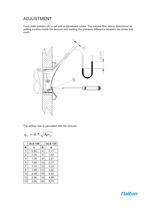
ADJUSTMENT Front plate position (A) is set with a adjustment screw. The volume flow rate is determined by setting a probe inside the devicev and reading the pressure difference between the probe and room. The airflow rate is calculated with the formula.
Abrir o catálogo na página 6
When the adjustment has been made, cover the screw with the plastic plug.
Abrir o catálogo na página 7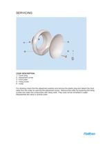
CODE DESCRIPTION 1 Cover plug 2 Adjustment screw 3 Front plate 4 Fixing screw 5 Collar For cleaning check first the adjustment position and remove the plastic plug and detach the front plate from the collar by opening the adjustment screw. Remove the collar by loosening the fixing screws and clean the components with damp cloth. They must not be immersed in water. Reassemble the valve in reverse order.
Abrir o catálogo na página 8
SUGGESTED SPECIFICATION ULE supply air valve shall have a detachable front plate and collar made of painted steel with a white (RAL 9010) standard colour. The collar shall have a screw fastening and incorporate a sealing gasket. Supply airflow rate and throw length shall be adjusted by turning the adjustment screw in the front plate. Pressure loss shall be selected at the same time as the flow pattern adjustment and balancing.
Abrir o catálogo na página 9
PRODUCT CODE ULE-D D = Connection size 100, 125 Specific CO = Colour W White (RAL 9010) X Special colour Code examble ULE-100, CO=W
Abrir o catálogo na página 10Todos os catálogos e folhetos técnicos da HALTON
-
 Halton Vita Cell Room (VCR)
2 Páginas
-
 Halton Rex Expander (RXP)
16 Páginas
-
 Halton CBD
8 Páginas
-
 FS Halton AHUs
28 Páginas
-
 Halton KCD
3 Páginas
-
 KVE-CM
7 Páginas
-
 KMC - MobiChef
5 Páginas
-
 Halton MobiChef
12 Páginas
-
 R6B
R6B9 Páginas
-
 Halton – Residential Ventilation System
20 Páginas
-
 Halton Vario
20 Páginas
-
 Halton FDS
7 Páginas
-
 Halton FDR
6 Páginas
-
 Halton FDI
6 Páginas
-
 Halton FDE
8 Páginas
-
 Halton FDC
5 Páginas
-
 ALE/ALU
8 Páginas
-
 AHF
AHF5 Páginas
-
 JTH
JTH4 Páginas
-
 Capture Jet solutions general brochure
12 Páginas
-
 FDC
FDC5 Páginas
-
 AFB
AFB7 Páginas
-
 TCG 2013
4 Páginas
-
 FCU 2013
6 Páginas
-
 KVS-C Kiosk Ventilation Systems
3 Páginas
-
 HFB - Airflow Management Damper
17 Páginas
-
 VHB - Active VAV Diffuser
7 Páginas
-
 TLD - Wall Diffuser Unit
9 Páginas
-
 FDB2 -
4 Páginas
-
 CPA - Passive Chilled Beam
13 Páginas
-
 CCC - Adaptable Active Chilled Beam
13 Páginas
-
 Product catalogue of air filtration
71 Páginas

Catálogos arquivados
-
 FCU Vertical Fancoil Unit
4 Páginas
-
 Halton ? AdaptableClimate
12 Páginas
-
 Halton ? Ventilation fire safety
12 Páginas
-
 Halton ? Chilled Beams
12 Páginas
-
 HALTON-POLLUSTOP
4 Páginas
-
 UNIPOINT
4 Páginas
-
 HALTON-CYCLOCELL CASSETTE CEILING
2 Páginas
-
 HALTON-KVD
6 Páginas
-
 HALTON-KCE
10 Páginas
-
 HALTON-KSK
6 Páginas
-
 KCJ
KCJ12 Páginas
-
 Halton - universal grilles
46 Páginas
-
 Halton - displacement design guide
13 Páginas
-
 Halton - beam design guide
31 Páginas
-
 Halton - air diffusion design guide
6 Páginas