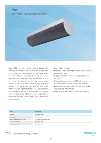
Excertos do catálogo

TLD Wall Diffuser Unit • Horizontal plane jet air supply • Cleaning of the terminal unit and supply ductwork • Directional nozzles with two-slot air path, which enabled by the detachable diffuser section deflect the air streams effectively • Installation of the diffuser on the wall in the Product models & Accessories vicinity of the ceiling • Plenum with duct connection on the back • Airflow rate measurement and adjustment • Plenum with duct connection on the side • Cover sleeve for exposed installations • Circular duct connection with gasket on the back or on the side of the plenum MATERIAL AND FINISHING PART Diffuser section Galvanised steel Attenuation material Mineral wool Cutting edges protected Cover sleeve Galvanised steel Painted in diffuser colour Coupling sleeve with gasket Galvanised steel Gasket of rubber compound Epoxy painted, Standard colour RAL 9010 Only diffuser section, special colours available Colour options: White RAL 9010, Grey RAL 7040 and Black TLD - Wall Diffuser Unit 242
Abrir o catálogo na página 1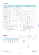
LpA values presented with room attenuation 4 dB (red 10m sab). When using room attenuation 8 dB (red 25m 2 - sab): LpA - 4dB. DPtot Total pressure drop, Pa Ld Distance from the supply unit, at which air jet detaches from ceiling, m dP_t Maximum DPtot (Pa), when a-weighted sound pressure level (Lp) is 35 dB(A) L0.2 Isotermal throw length, m when residual velocity of supply air jet 0,2 m/s Room temperature (Tr) = 24 °C Supply air temperature (Ta) 16 °C = Pa Supply air cooling capacity, W LpA A-weighted sound pressure level, reduced by total equivalent absorption surface of 10m 2, dB(A) red...
Abrir o catálogo na página 2
LpA values presented with room attenuation 4 dB (red 10m sab). When using room attenuation 8 dB (red 25m 2 - sab): LpA - 4dB. DPtot Total pressure drop, Pa Ld Distance from the supply unit, at which air jet detaches from ceiling, m dP_t Maximum DPtot (Pa), when a-weighted sound pressure level (Lp) is 35 dB(A) L0.2 Isotermal throw length, m when residual velocity of supply air jet 0,2 m/s Room temperature (Tr) = 24 °C Supply air temperature (Ta) 16 °C = Pa Supply air cooling capacity, W LpA A-weighted sound pressure level, reduced by total equivalent absorption surface of 10m 2, dB(A) red...
Abrir o catálogo na página 3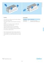
The nozzles of the diffuser direct the airflow obliquely toward the ceiling surface. Cover sleeve Cover sleeve for exposed installation (only for TLD/B plenum) The supply air pattern can be directed by rotating the nozzles. Direction of the supply air jet does not affect the pressure drop or the airflow rate. The recommended maximum air temperature difference between supply and room air is 8 0C. The maximum recommended operating temperature for the plastic material is 60 °C. Note: The airflow pattern data has been prepared for a wall installation with a distance of 200 mm from the ceiling...
Abrir o catálogo na página 4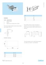
diffuser section Plenum CODE DESCRIPTION Measurement and adjustment module Do not fasten screws or rivets in the section at The recommended installation distance below ceiling distance K1 from the front edge of the plenum, in order to keep the section clear for diffuser section (1) fastening. Installation opening The recommended minimum safety distance before the supply unit is 3xD (D = duct diameter). TLD - Wall Diffuser Unit 246
Abrir o catálogo na página 5
The supply flow rate is determined by using measurement and adjustment module MSM. The tubes and control spindle are passed through the nozzles of the diffuser section, which is then replaced. Measure the differential pressure with a manometer. The flow rate is calculated using the formula below. Adjust the airflow rate by rotating the control spindle until the desired setting is achieved. Lock the damper position with a screw. Replace the tubes and spindle in the diffuser section. The k factor for installations with different safety p distances (D= duct diameter) is as follows. ^ The...
Abrir o catálogo na página 6
Pressure drop, throw pattern and sound data Selection example : Installation 200 mm below ceiling TLD -Wall Diffuser Unit
Abrir o catálogo na página 7
Pressure drop, throw pattern and sound data TLD -Wall Diffuser Unit
Abrir o catálogo na página 8
Product code Open the diffuser section, and remove the measurement and adjustment module by gently pulling from the shaft (not from the control spindle or measurement tubes). Diffuser section Wipe the parts with a damp cloth, instead of TLB Plenum (with MSM module) TLB Plenum (without MSM module) Reassemble the measurement and adjustment TLC Plenum (with MSM module) module by pushing the shaft until it meets the TLC Plenum (without MSM module) stopper. The diffuser section is replaced by pushing it into the D = Diameter of duct connection plenum until the springs lock. Suggested...
Abrir o catálogo na página 9Todos os catálogos e folhetos técnicos da HALTON
-
 Halton Vita Cell Room (VCR)
2 Páginas
-
 Halton Rex Expander (RXP)
16 Páginas
-
 Halton CBD
8 Páginas
-
 FS Halton AHUs
28 Páginas
-
 Halton KCD
3 Páginas
-
 KVE-CM
7 Páginas
-
 KMC - MobiChef
5 Páginas
-
 Halton MobiChef
12 Páginas
-
 R6B
R6B9 Páginas
-
 Halton – Residential Ventilation System
20 Páginas
-
 Halton Vario
20 Páginas
-
 Halton FDS
7 Páginas
-
 Halton FDR
6 Páginas
-
 Halton FDI
6 Páginas
-
 Halton FDE
8 Páginas
-
 Halton FDC
5 Páginas
-
 ALE/ALU
8 Páginas
-
 AHF
AHF5 Páginas
-
 JTH
JTH4 Páginas
-
 Capture Jet solutions general brochure
12 Páginas
-
 FDC
FDC5 Páginas
-
 AFB
AFB7 Páginas
-
 TCG 2013
4 Páginas
-
 FCU 2013
6 Páginas
-
 KVS-C Kiosk Ventilation Systems
3 Páginas
-
 HFB - Airflow Management Damper
17 Páginas
-
 VHB - Active VAV Diffuser
7 Páginas
-
 FDB2 -
4 Páginas
-
 CPA - Passive Chilled Beam
13 Páginas
-
 CCC - Adaptable Active Chilled Beam
13 Páginas
-
 Product catalogue of air filtration
71 Páginas

Catálogos arquivados
-
 FCU Vertical Fancoil Unit
4 Páginas
-
 Halton ? AdaptableClimate
12 Páginas
-
 Halton ? Ventilation fire safety
12 Páginas
-
 Halton ? Chilled Beams
12 Páginas
-
 HALTON-POLLUSTOP
4 Páginas
-
 UNIPOINT
4 Páginas
-
 HALTON-CYCLOCELL CASSETTE CEILING
2 Páginas
-
 HALTON-KVD
6 Páginas
-
 HALTON-KCE
10 Páginas
-
 HALTON-KSK
6 Páginas
-
 KCJ
KCJ12 Páginas
-
 Halton - universal grilles
46 Páginas
-
 Halton - displacement design guide
13 Páginas
-
 Halton - beam design guide
31 Páginas
-
 Halton - air diffusion design guide
6 Páginas