- Catalogs
- ZEALUX France
- R290 SERIES
- Company
- Products
- Catalogs
- News & Trends
- Exhibitions
R290 SERIES
1 /44Pages
R290 SERIES
1 /44Pages
Catalog excerpts
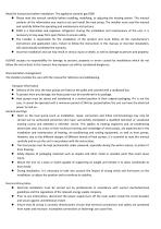
Read the instructions before installation. The appliance contains gas R290 • Please read this manual carefully before installing, modifying, or adjusting the heating system. This manual contains all the information you need to use and install the heat pump. The installer must read the manual and carefully follow the operating and maintenance instructions. • R290 is a flammable and explosive refrigerant. During the installation and maintenance of the unit, it is necessary to stay away from open flames to ensure safety. • The installer is responsible for the installation of the product and must...
Open the catalog to page 3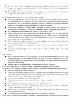
Connect the device to earth, in compliance with local laws and regulations. Do not connect the earth cable to the gas or water pipe, or to the lightning protection cable. This could cause a fire. Incomplete grounding may result in electric shock. • When wiring the power supply, ensure that the terminal block is securely fastened. If the terminal block is not tightened sufficiently, the terminals may overheat and cause a fire. HFC Gaseous Refrigerant comply with standards and regulation (EU) No 517/2014 • Training and certification, the operator of the relevant application shall ensure that the...
Open the catalog to page 4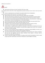
• Risk of electric shock due to incorrect connection to the mains supply. Non-compliance with the rules of the art when making electrical connections can lead to the risk of electric shock and material damage. • Be sure to install protective circuit breakers in accordance with local laws and regulations. Failure to install a protective device may result in a risk of electric shock and fire. • Before working on the heat pump, switch off the power supply via the circuit breaker. • When the service panels are removed, the user must take all necessary precautions to avoid any incident. • Never leave...
Open the catalog to page 5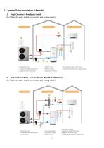
P20=7(Domestic water tank & room cooling and heating model) Monobloc Unit 2.Controller (Monobloc Unit) Magnetic Particle Filter 7,Aotumatic water refill valve 8 Differential pressure bypass valve 1.2. Dual Circulation Pump - Low Loss Header (Retrofit of Old System) P20=7(Domestic water tank & room cooling and heating model) Expansion Vessel Monobloc Unit Aotumatic water refill valve Circulation Pump Controller (Monobloc Unit) Magnetic Particle Filter Differential pressure bypass valve
Open the catalog to page 8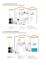
Monobloc Unit Controller (Monobloc Unit) 7 3 Way Valve 4.Buffer Tank 8.Aotumatic water refill valve 1 Circulation Pump Magnetic Particle Filter 6.DHW Cylinder 10.Differential pressure bypass valve 2. Controller (Monobloc Unit) 5. Heat Exchangerfor pool 6.3 Way Valve Circulation water pump 9. Aotumatic water refill valve 10. Magnetic Particle Filter 11 Differential pressure bypass valve
Open the catalog to page 9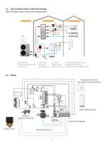
1.5. Dual Circulation Pump - Under Floor Heating P20=3( Domestic water tank & room heating model) Monobloc Unit > Controller (Monobloc Unit) 3 Way Valve ^ Buffer Tank . Controller 10.Aotumatic water refill valve : Mixer Valve DHW Cylinder .Magnetic Particle Filter 6 Circulation Pump 9.Expansion Vessel 12.Differential pressure bypass valve 3 Way Valve Remote Controller (included with heat pump) CN16 Pipeline Electric Heating XT1 I I I xt; I I I Secondary Pump DHW Tank Sensor Link Switch Signal 3
Open the catalog to page 10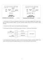
1. For terminals 1 to 3, they are connected to circulator pump. For the models integrated with circulator pump, they are already connected in default. If you have secondary circulator pump, you can also connect to these terminals. 2. For the terminal 4 & 5, they are control signal for backup heater(Signal). 3. For terminals 6 to 8, they are for the three way valve. (6: Live wire, 7: Control wire, 8: Neutral wire) 4. For terminal 9 to 10, they work as a switch to control the heat pump. They are connected in default. If you need to control the heat pump by additional switch, you can connect your...
Open the catalog to page 11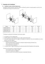
Providing the required clearance around the outdoor unit allows the system to operate properly, since this is the renewable input energy for the system (free air). *The distance mentioned in the drawing is the minimum request. • The appliance can't be installed indoor. • Place the appliance on anti-vibration studs on a stable, solid and level surface. • This surface must be able to bear the weight of the appliance (in particular in the case of installation on a roof, a balcony or any other support). • The appliance must not be installed: >With the blowing towards a permanent or temporary obstacle...
Open the catalog to page 12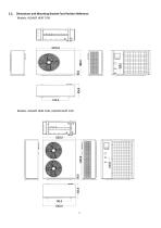
2.2. Dimensions and Mounting Bracket Foot Position Reference Models: ALSAVO HEAT 07i9 Models: ALSAVO HEAT 10i9, ALSAVO HEAT 12i9
Open the catalog to page 13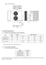
Models: ALSAVO HEAT 16i9T 3.1. References for protecting devices and cable specification *Please note that these sizes are for guidance only and may differ dependent on pipe run, pressure losses within the system and number of bends.
Open the catalog to page 14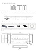
Expansion Vessel & Buffer Tank Selection Model ALSAVO HEAT 07i9 ALSAVO HEAT 10i9 ALSAVO HEAT 12i9 ALSAVO HEAT 16i9T If the system volume exceeds that shown in the table, or if the head height exceeds 7 meters, an additional expansion vessel must be installed. 3.4. Flow Rate Model Advise water flux (m3/h) The condensation pan is only used to collect condensation water generated when the heat pump is running and to be removed by the drain pipe.
Open the catalog to page 15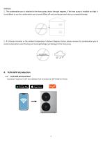
1. The condensation pan is attached to the heat pump chassis through magnets, if the heat pump is installed too high, it is prohibited to use the condensation pan to avoid falling off and causing personal injury or property damage. 2. If it freezes in winter or the ambient temperature is below 0 degrees Celsius, please remove the condensation pan to avoid condensation water freezing and causing blockage and damage to the heat pump. TUYA Wifi APP Download Download "Tuya Smart" APP from GOOGLE PLAY for Android or APP STORE for iPhone.
Open the catalog to page 16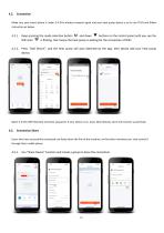
Make sure your smart phone is under 2.4 GHz wireless network signal and your heat pump device is on to use TUYA and follow instruction as below. 4.2.1. Keep pressing the mode selection button and down buttons on the control panel until you see the WIFI icon is flicking, that means the heat pump is waiting for the connection of WIFI. 4.2.2. Press "Add Device", and the heat pump will auto detected by the app, then please add your heat pump device. Select 2.4 GHz WIFI Network and enter password. If your device is on, press Next directly, and it will connect successfully. Connection Share Users who...
Open the catalog to page 17All ZEALUX France catalogs and technical brochures
 Inverter Dehumidifier
2 Pages
 Fan coil units
17 Pages
 Inverboost
6 Pages
 Pool & SPA Heat Pumps
47 Pages
 Multi-funtion Heat Pumps
24 Pages
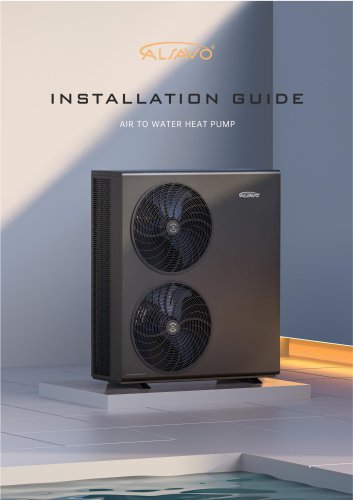 AIR TO WATER HEAT PUMP
77 Pages
 POOL HEAT PUMP
20 Pages
 RESIDENTIAL HEAT PUMP
8 Pages
 House catalog
24 Pages
 2025-zealux-pool-catalog
17 Pages
- Residential heat pump
- Air source heat pump
- Outdoor heat pump
- Air/water heat pump
- Inverter heat pump
- Energy rating heat pump
- Industrial dehumidifier
- Smart heat pump
- Split heat pump
- Commercial heat pump
- Monobloc heat pump
- Industrial fan coil
- Class A+++ heat pump
- Reversible heat pump
- Hot water heat pump
- Mobile dehumidifier
- Floor dehumidifier
- WiFi heat pump
- Swimming pool heat pump