- Catalogs
- Vitrum Design
- Vitrum Scene Control Panel
Vitrum Scene Control Panel

Vitrum Scene Control Panel
- Power Supply: 240V/50Hz
- Energy Consumption: <1W
- Operating Temperature: 0-40°C
- Wireless Z-Wave Modem Frequency: 868.4 MHz
- Range in Open Air: 20 meters
- IP Protection Rating: IP 40
Catalog excerpts

HOME CONTROL Vitrum Scene Control Ponol
Open the catalog to page 1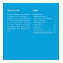
DeSCRIPTION INDEX A Vitrum Scene differs from Dimmer and On-Off devices for this reason: there is no exit used for directly control a load. It’s used for creating lighting scenarios in your house: simply pressing a button, you can switch on and off (in case of lamp connected to a Vitrum dimmer you can select the light level too) the lights of your scenary. 0. Before starting. . . . . . . . . . . . . . . . . 3 1. Electrical connections. . . . . . . . . . . . 4 2. Positioning the glass decor panel. . . 6 3. Vitrum is intelligent . . . . . . . . . . . . . 8 4. Advanced functions. . . . . . . . ....
Open the catalog to page 2
0. BEFORE STARTING The Vitrum system that you have purchased is designed for connection to your existing 240V power supply circuit. Before commencing installation, ensure that the mains power supply had been disconnected by setting the main switch on your electricity meter to OFF. Do not re-connect the power supply and start using Vitrum until all connections have been correctly completed and the Vitrum unit has been inserted into the wallmounting box. Vitrum must be installed by a professional electrician who is qualified to operate on electrical power circuits in full compliance with all current...
Open the catalog to page 3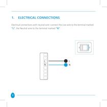
1. ELECTRICAL CONNECTIONS Electrical connections with neutral wire: connect the Live wire to the terminal marked “L”, the Neutral wire to the terminal marked “N”: 4
Open the catalog to page 4
IMPORTANT After connecting, check that the wires are correctly positioned inside the wallmounting box. When securing Vitrum to the wall-mounting box, use the screws supplied and note that the maximum torque to be used when tightening the screws in the embedding box is 0.8 Nm. In addition, the surface of the wall for at least 2 cm surrounding the embedding box must be as flat and smooth as possible, and must not have any rough patches and/or bumps that protrude more than 1 mm. If the screws are not tightened with the torque specified, or if the embedding box is installed on unsuitable surfaces,...
Open the catalog to page 5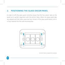
2. POSITIONING THE GLASS DECOR PANEL In order to refit the glass panel correctly, ensure that the four plastic tabs on the panel are in perfect alignment with the anchor holes. When the glass panel tabs are aligned with the holes, press the four corners of the glass panel evenly until it is fully inserted into the wall-mounting box. Anchor holes on electronic section 6
Open the catalog to page 6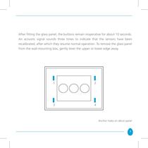
After fitting the glass panel, the buttons remain inoperative for about 10 seconds. An acoustic signal sounds three times to indicate that the sensors have been recalibrated, after which they resume normal operation. To remove the glass panel from the wall-mounting box, gently lever the upper or lower edge away. Anchor holes on décor panel 7
Open the catalog to page 7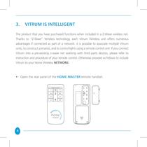
3. VITRUM IS INTELLIGENT The product that you have purchased functions when included in a Z-Wave wireless net. Thanks to “Z-Wave” Wireless technology, each Vitrum Wireless unit offers numerous advantages if connected as part of a network: it is possible to associate multiple Vitrum units, to construct scenarios, and to control lights using a remote control unit. If you connect Vitrum into a pre-existing z-wave net working with third parts devices, please refer to instruction and procedure of your remote control. Otherwise proceed as follows to include Vitrum to your Home Wireless Network: • Open...
Open the catalog to page 8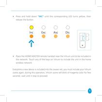
• Press and hold down “INC” until the corresponding LED turns yellow, then release the button • Place the HOME MASTER remote handset near the Vitrum unit to be included in the network. Touch any of the keys on Vitrum to include the unit in the home wireless network. Everytime a new device is included into the zwave net, you must include your Vitrum scene again; during this operation, Vitrum scene will blink of magenta color for few seconds: wait until it stop to proceed. 9
Open the catalog to page 9
• When all the Vitrum units have been added to the network, press the “INC” key again until the LED switches off. Now you will see that the illuminated rings around the Vitrum touch keys no longer light red when changing from one status to the next. NotE A Vitrum unit cannot be added to the network if it has already been included in a different network. In this case, it is necessary to perform the factory reset procedure -> see Paragraph 7). 10
Open the catalog to page 10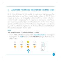
4. ADVANCED FUNCTIONS: CREATION OF CONTROL LOGIC On all Vitrum Wireless units, it is possible to create control logic processes that associate the button on one Vitrum module to other buttons on OTH ER Vitrum modules For creating a control logic, the modules must first be included in the home wireless network -> see paragraph 3. It’s very simple to create a scene. First of all you need to associate your Vitrum Scene to all the other buttons of other Vitrum that you desire be part of the scene (max 8 Vitrum). So, every time you’ll push a scene (buttons 1,2,3 or 4) you will activate a light level...
Open the catalog to page 11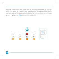
Press the buttons of the other Vitrum that are physically connected to the lighs you want to be part of the scene. The LED corresponding to the selected button/channel will flash magenta until the ‘association’ process has been completed. When finished press briefly again the “ASC” button of remote control 12
Open the catalog to page 12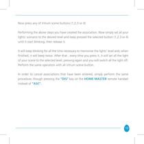
Now press any of Vitrum scene buttons (1,2,3 or 4) Performing the above steps you have created the association. Now simply set all your lights’ scenario to the desired level and keep pressed the selected button (1,2,3 or 4) until it start blinking; then release it. It will keep blinking for all the time necessary to memorize the lights’ level and, when finished, it will beep twice. After that , every time you press it, it will set all the light of your scene to the selected level; pressing again and you will switch all the light off. Perform the same operation with all Vitrum scene button. In...
Open the catalog to page 13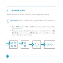
Proceed as follows to reset the Vitrum unit to the original factory settings: A. EXCLUSION from the home network using the HOME MASTER remote han- • Press "EXC" on the HOME MASTER remote handset and wait until the • Press and hold down the leftmost button on the multi-channel Vitrum unit (EU Standard), or the topmost key (BS Standard) or the central key on single- channel units, for at least 8 seconds
Open the catalog to page 14All Vitrum Design catalogs and technical brochures
 Vitrum design
72 Pages
 Catalogue 2014
52 Pages
Archived catalogs
 Vitrum MAster On-Off Wireless
20 Pages
 Vitrum II DIN On-Off Wireless
11 Pages
 Roller Blind
28 Pages
 Warnings
4 Pages
 Home Master Remote Handset
24 Pages
 Vitrum Dimmer Classic
24 Pages
 Vitrum Dimmer Wireless
32 Pages
 Vitrum Satellite Wireless
28 Pages
 Vitrum On-Off Classic
16 Pages
 Vitrum On-Off Wireless
24 Pages