- Catalogs
- Vitrum Design
- Vitrum Satellite Wireless
Vitrum Satellite Wireless

Vitrum Satellite Wireless
The Vitrum Satellite Wireless is a device designed to control loads connected to other Vitrum devices from different positions. It is cost-effective as it lacks a dimmer or relay onboard.
0. Before Starting
Ensure the mains power supply is disconnected before installation. Vitrum must be installed by a qualified electrician. Follow the circuit diagrams provided and ensure secure connections. Avoid installing near heat sources or in high humidity.
1. Electrical Connections
Connect the live wire to terminal 'L' and the neutral wire to terminal 'N'. Ensure wires are correctly positioned and use the supplied screws with a maximum torque of 0.8 nm.
2. Positioning the Glass Decor Panel
Align the glass panel tabs with anchor holes and press evenly. After fitting, buttons are inoperative for 10 seconds while sensors recalibrate.
3. Vitrum is Intelligent
Vitrum units function within a Z-Wave wireless network, allowing for multiple unit associations and remote control. Follow specific steps to include Vitrum in your network.
4. Advanced Functions
Create control logic processes to associate buttons across Vitrum modules. Associations are limited to separate modules and depend on the number of channels.
5. Setting Functions
Configure each channel of Vitrum Satellite to match the associated channel type (Dimmer, On-Off Switch, or Push Button). Follow specific steps to change configurations.
6. Disabling Eco Mode
Eco Mode is enabled by default. To disable, access the configuration menu and toggle the setting.
7. Factory Reset
Reset the Vitrum unit to factory settings via the HOME MASTER remote handset or a hidden button.
8. Supervision
Use the HOME MASTER app for iPhone or iPad for supervision. The identification function is indicated by magenta flashing rings.
9. Compatibility
Vitrum devices are Z-Wave certified and can interact with other certified devices, allowing system expansion.
10. Compliance with EC Directives
Vitrum units comply with European directives E.M.C.:2004/108/CE and R&TTE:1999/5/CE.
Main Technical Specifications
Power supply: 240V/50Hz
Energy consumption: <1W
Operating temperature: 0-40°C
Wireless frequency: 868.4 MHz
Communication range: 20 meters
Protection rating: IP 40
For more information, visit www.vitrum.com.
Catalog excerpts

EN H O M E C O N T R O L Vitrum Satellite Wireless INSTALLATION AND OPERATION
Open the catalog to page 1
Definition A Vitrum Satellite differs from Dimmer and On-Off devices for this reason: there is no exit used for directly control a load. It’s used in all the situations in which you need to control a load that is connected to another Vitrum from a different position. Being without dimmer or relè onboard, it costs less than Vitrum Dimmer Wireless or Vitrum On-Off Wireless. INDEX 0. Before starting. . . . . . . . . . . . . . . . . 3 1. Electrical connections. . . . . . . . . . . . 4 2. Positioning the glass decor panel. . . . 6 3. Vitrum is intelligent . . . . . . . . . . . . . 8 4. Advanced functions....
Open the catalog to page 2
0. BEFORE STARTING The Vitrum system that you have purchased is designed for connection to your existing 240V power supply circuit. Before commencing installation, ensure that the mains power supply had been disconnected by setting the main switch on your electricity meter to OFF. Do not re-connect the power supply and start using Vitrum until all connections have been correctly completed and the Vitrum unit has been inserted into the wall-mounting box. Vitrum must be installed by a professional electrician who is qualified to operate on electrical power circuits in full compliance with all current...
Open the catalog to page 3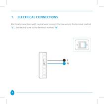
1. ELECTRICAL CONNECTIONS Electrical connections with neutral wire: connect the Live wire to the terminal marked “L”, the Neutral wire to the terminal marked “N”. 4
Open the catalog to page 4
IMPORTANT After connecting, check that the wires are correctly positioned inside the wall-mounting box. When securing Vitrum to the wall-mounting box, use the screws supplied and note that the maximum torque to be used when tightening the screws in the embedding box is 0.8 Nm. In addition, the surface of the wall for at least 2 cm surrounding the embedding box must be as flat and smooth as possible, and must not have any rough patches and/or bumps that protrude more than 1 mm. If the screws are not tightened with the torque specified, or if the embedding box is installed on unsuitable surfaces,...
Open the catalog to page 5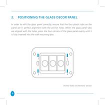
2. POSITIONING THE GLASS DECOR PANEL In order to refit the glass panel correctly, ensure that the four plastic tabs on the panel are in perfect alignment with the anchor holes. When the glass panel tabs are aligned with the holes, press the four corners of the glass panel evenly until it is fully inserted into the wall-mounting box. Anchor holes on electronic section 6
Open the catalog to page 6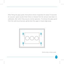
After fitting the glass panel, the buttons remain inoperative for about 10 seconds. An acoustic signal sounds three times to indicate that the sensors have been recalibrated, after which they resume normal operation. To remove the glass panel from the wall-mounting box, gently lever the upper or lower edge away. Anchor tabs on décor panel 7
Open the catalog to page 7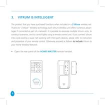
3. VITRUM IS INTELLIGENT The product that you have purchased functions when included in a Z-Wave wireless net. Thanks to “Z-Wave” Wireless technology, each Vitrum Wireless unit offers numerous advantages if connected as part of a network: it is possible to associate multiple Vitrum units, to construct scenarios, and to control lights using a remote control unit. If you connect Vitrum into a pre-existing z-wave net working with third parts devices, please refer to instruction and procedure of your remote control. Otherwise proceed as follows to include Vitrum to your Home Wireless Network: • Open...
Open the catalog to page 8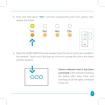
• Press and hold down “INC” until the corresponding LED turns yellow, then release the button. • Place the HOME MASTER remote handset near the Vitrum unit to be included in the network. Touch any of the keys on Vitrum to include the unit in the home wireless network. Vitrum indicates that it has been connected to the network by flashing the yellow LEDs three times and switching on all the lights connected to the unit. 9
Open the catalog to page 9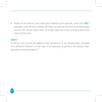
• When all the Vitrum units have been added to the network, press the “INC” key again until the LED switches off. Now you will see that the illuminated rings around the Vitrum touch keys no longer light red when changing from one status to the next. NotE A Vitrum unit cannot be added to the network if it has already been included in a different network. In this case, it is necessary to perform the factory reset procedure (see Paragraph 7).. 10
Open the catalog to page 10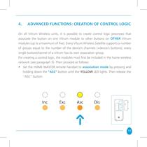
4. ADVANCED FUNCTIONS: CREATION OF CONTROL LOGIC On all Vitrum Wireless units, it is possible to create control logic processes that associate the button on one Vitrum module to other buttons on OTHER Vitrum modules (up to a maximum of five). Every Vitrum Wireless Satellite supports a number of groups equal to the number of the device’s channels (=device’s buttons); every single button/channel of a Vitrum has its own association group. For creating a control logic, the modules must first be included in the home wireless network (see paragraph 3). Then proceed as follows: • Set the HOME MASTER...
Open the catalog to page 11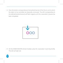
• Press the button corresponding to the button/channel of the Vitrum unit to which the lights to be controlled are physically connected. The LED corresponding to the selected button/channel will flash magenta until the ‘association’ process has been completed. • On the HOME MASTER remote handset, press the ‘association’ touch key briefly. The LED will light red. 12
Open the catalog to page 12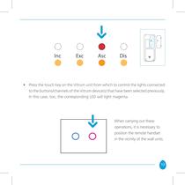
• Press the touch key on the Vitrum unit from which to control the lights connected to the buttons/channels of the Vitrum device(s) that have been selected previously. In this case, too, the corresponding LED will light magenta. When carrying out these operations, it is necessary to position the remote handset in the vicinity of the wall units. 13
Open the catalog to page 13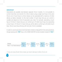
IMPORTANT Associations are possible only between separate Vitrum modules. It is not possible to control more than one channel of a Vitrum device using a single touch key on the same Vitrum unit. A touch key on a Vitrum device can be associated with a maximum of other devices as below indicated. So the total number of touch keys that you can control is variable and depend on kind of association you make. For example: associating a touch key to 10 Vitrum I means that you can control up to 10 other touch keys; but associating a touch key to 10 Vitrum IV means that you will be able to control up...
Open the catalog to page 14All Vitrum Design catalogs and technical brochures
 Vitrum design
72 Pages
 Catalogue 2014
52 Pages
Archived catalogs
 Vitrum MAster On-Off Wireless
20 Pages
 Vitrum II DIN On-Off Wireless
11 Pages
 Vitrum Scene Control Panel
20 Pages
 Roller Blind
28 Pages
 Warnings
4 Pages
 Home Master Remote Handset
24 Pages
 Vitrum Dimmer Classic
24 Pages
 Vitrum Dimmer Wireless
32 Pages
 Vitrum On-Off Classic
16 Pages
 Vitrum On-Off Wireless
24 Pages