- Catalogs
- Vitrum Design
- Vitrum Dimmer Wireless
Vitrum Dimmer Wireless

Vitrum Dimmer Wireless
- With Neutral Wire: Connect live wire to 'L', neutral to 'N', and lights to '1..3'.
- Without Neutral Wire: For loads over 40W, use supplied jumpers to connect 'N'.
- Special Lamps: Some lamps may require a neutral wire.
- Power Supply: 240V/50Hz for all models.
- Energy Consumption: Less than 1W for all models.
- Operating Temperature: 0-40°C for all models.
- Total Load Capacity: Varies by mode: Trailing Edge Mode up to 300W, Leading Edge Mode up to 200W.
- Wireless Z-Wave Modem Frequency: 868.4 MHz.
- Z-Wave Modem Open Air Range: 20 meters.
- Protection Features: Includes short-circuit protection, overheating protection, and automatic trailing/leading edge selection.
- Protection Rating: IP 40.
Catalog excerpts

HOME CONTROL Vitrum Dimmer UUireless
Open the catalog to page 1
INDEX 0. Before starting. . . . . . . . . . . . . . . . . 3 1. Electrical connections. . . . . . . . . . . . 4 2. Positioning the glass decor panel. . . . 9 3. Eco-Vitrum. . . . . . . . . . . . . . . . . . . 11 4. Vitrum is intelligent . . . . . . . . . . . . 13 5. Type of lamp. . . . . . . . . . . . . . . . . . 16 6. Disabling Eco Mode . . . . . . . . . . . . 19 7. Advanced functions. . . . . . . . . . . . 22 8. Factory reset. . . . . . . . . . . . . . . . . . 26 9. Protective devices. . . . . . . . . . . . . . 28 10. Supervision. . . . . . . . . . . . . . . . . . 29 11. Compatibility. . . ....
Open the catalog to page 2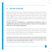
0. BEFORE STARTING The Vitrum system that you have purchased is designed for connection to your existing 240V power supply circuit. Before commencing installation, ensure that the mains power supply had been disconnected by setting the main switch on your electricity meter to OFF. Do not re-connect the power supply and start using Vitrum until all connections have been correctly completed and the Vitrum unit has been inserted into the wall-mounting box. Vitrum must be installed by a professional electrician who is qualified to operate on electrical power circuits in full compliance with all current...
Open the catalog to page 3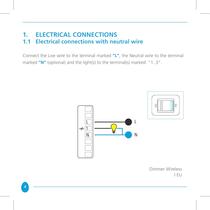
1. ELECTRICAL CONNECTIONS 1.1 Electrical connections with neutral wire Connect the Live wire to the terminal marked “L”, the Neutral wire to the terminal marked “N” (optional) and the light(s) to the terminal(s) marked “1..3”. Dimmer Wireless I EU 4
Open the catalog to page 4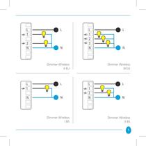
Dimmer Wireless Dimmer Wireless Dimmer Wireless Dimmer Wireless
Open the catalog to page 5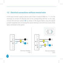
1.2 Electrical connections without neutral wire In the case of power supply to devices with a load in excess of 40W on “1”, it is not necessary to connect the Neutral wire to the corresponding terminal: in this case, connect the terminal marked “N” as shown in the figures below using the special jumpers (supplied) and connecting the neutral directly to the terminal of one of the lights connected to the system. Dimmer Wireless I EU 6 Dimmer Wireless II EU
Open the catalog to page 6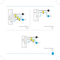
Dimmer Wireless Dimmer Wireless Dimmer Wireless
Open the catalog to page 7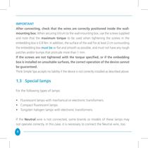
IMPORTANT After connecting, check that the wires are correctly positioned inside the wallmounting box. When securing Vitrum to the wall-mounting box, use the screws supplied and note that the maximum torque to be used when tightening the screws in the embedding box is 0.8 Nm. In addition, the surface of the wall for at least 2 cm surrounding the embedding box must be as flat and smooth as possible, and must not have any rough patches and/or bumps that protrude more than 1 mm. If the screws are not tightened with the torque specified, or if the embedding box is installed on unsuitable surfaces,...
Open the catalog to page 8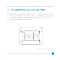
2. POSITIONING THE GLASS DECOR PANEL In order to refit the glass panel correctly, ensure that the four plastic tabs on the panel are in perfect alignment with the anchor holes. When the glass panel tabs are aligned with the holes, press the four corners of the glass panel evenly until it is fully inserted into the wall-mounting box. Anchor holes on electronic section 9
Open the catalog to page 9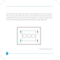
After fitting the glass panel, the buttons remain inoperative for about 10 seconds. An acoustic signal sounds three times to indicate that the sensors have been recalibrated, after which they resume normal operation. To remove the glass panel from the wall-mounting box, gently lever the upper or lower edge away. Anchor tabs on décor panel 10
Open the catalog to page 10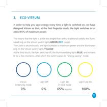
3. ECO-VITRUM In order to help you save energy every time a light is switched on, we have designed Vitrum so that, at the first fingertip touch, the light switches on at about 65% of maximum power. This means that the light is a little less bright than with a traditional switch; the illuminated ring on the Vitrum switch lights GREEN (ECO mode). Then, with a second touch, the light increases to maximum power and the illuminated ring on the Vitrum switch lights YELLOW. At the third touch, the light switches off; the illuminated ring lights BLUE, and remains lit for a few moments, after which the...
Open the catalog to page 11
When passing from one mode to the next, the illuminated ring will light RED for a moment. This indicates that Vitrum is operating in STAND ALONE mode and has not yet been connected to your home wireless network. IMPORTANT If the illuminated ring lights RED and flashes continuously, this indicates that the internal safety devices have cut in automatically. This may be caused by connection of loads that are in excess of the loads that can be handled by the Dimmer or by other malfunctions (see “Safety Devices”). 12
Open the catalog to page 12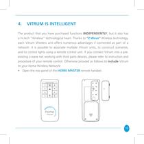
4. VITRUM IS INTELLIGENT The product that you have purchased functions INDEPENDENTLY, but it also has a hi-tech “Wireless” technological heart. Thanks to “Z-Wave” Wireless technology, each Vitrum Wireless unit offers numerous advantages if connected as part of a network: it is possible to associate multiple Vitrum units, to construct scenarios, and to control lights using a remote control unit. If you connect Vitrum into a preexisting z-wave net working with third parts devices, please refer to instruction and procedure of your remote control. Otherwise proceed as follows to include Vitrum to...
Open the catalog to page 13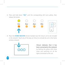
• Press and hold down “INC” until the corresponding LED turns yellow, then release the button. • Place the HOME MASTER remote handset near the Vitrum unit to be included in the network. Touch any of the keys on Vitrum to include the unit in the home wireless network. Vitrum indicates that it has been connected to the network by flashing the yellow LEDs three times and switching on all the lights connected to the unit. 14
Open the catalog to page 14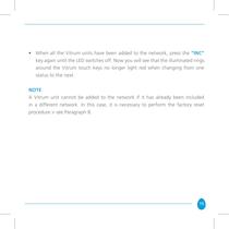
• When all the Vitrum units have been added to the network, press the “INC” key again until the LED switches off. Now you will see that the illuminated rings around the Vitrum touch keys no longer light red when changing from one status to the next. NotE A Vitrum unit cannot be added to the network if it has already been included in a different network. In this case, it is necessary to perform the factory reset procedure > see Paragraph 8. 15
Open the catalog to page 15All Vitrum Design catalogs and technical brochures
 Vitrum design
72 Pages
 Catalogue 2014
52 Pages
Archived catalogs
 Vitrum MAster On-Off Wireless
20 Pages
 Vitrum II DIN On-Off Wireless
11 Pages
 Vitrum Scene Control Panel
20 Pages
 Roller Blind
28 Pages
 Warnings
4 Pages
 Home Master Remote Handset
24 Pages
 Vitrum Dimmer Classic
24 Pages
 Vitrum Satellite Wireless
28 Pages
 Vitrum On-Off Classic
16 Pages
 Vitrum On-Off Wireless
24 Pages