


Uponor Minitec technical guide
Uponor Minitec technical guide
Uponor Minitec is a versatile underfloor heating and cooling system designed for fast installation and short heat-up times. It is suitable for integration into existing buildings due to its low element height of approximately 1 cm, allowing installation on existing screed, timber, or tiled floors.
The system uses Uponor PE-Xa pipes (9.9 x 1.1 mm) laid in nub foil elements. The foil has punched holes for easy spreading and bonding of the levelling compound. The system's total installation height can be as low as 15 mm, allowing for quick temperature adjustments and operation at low heating water temperatures.
- Uponor PE-Xa Pipe: Flexible pipes held in place by the foil's naps, suitable for 90° and 45° bends.
- Edge Insulation Strip: Self-adhesive strip for sealing along walls and floors.
- Movement Joint Profile: Components for mounting in doorways and creating joint profiles.
- Foil Element: Sturdy elements that can be walked on immediately, suitable for all room geometries.
Floor surface temperatures must adhere to DIN EN 1264 standards, with maximums of 29°C in comfort zones and 35°C in edge zones. The system is designed for energy efficiency, providing comfort even at reduced room air temperatures.
Design tables provide approximate calculations for pipe spacing and maximum heating circuit size. Proper planning and calculation are essential. The tables consider factors like thermal resistance, room temperature, and flow temperature.
Installation should be performed by expert installers, following specific assembly instructions. The process includes mounting edge strips, installing foil elements, and connecting pipes.
- Pipe Dimensions: 9.9 x 1.1 mm
- Material: PE-Xa, oxygen-tight according to DIN 4726
- Max Operating Pressure: 19.1 bar at 20°C, 8.8 bar at 70°C
- Foil Element Material: Polystyrene, with a max traffic load of 5.0 kN/m²
Catalog excerpts

Uponor Minitec technical guide U N D E R F LO O R H E AT I N G A N D COOLING
Open the catalog to page 1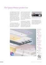
The Uponor Minitec product line Fast installation, short heat-up time: Uponor Minitec offers you a range of advantages. The Uponor Minitec foil element for aying the Uponor l PE-Xa pipes 9.9 x 1.1 mm can be installed on any existing screed, timber or tiled floor. Thanks to the low element height of around one centimetre, it is particularly suitable for integration into existing buildings. The nub foil is equipped with punched holes in and between the nubs, which ensure, that the levelling compound can spread easily and bonds firmly with the sub- structure. The rear side of the elements is equipped...
Open the catalog to page 2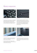
Minitec components Uponor Minitec foil element Uponor PE-Xa pipe The sturdy Uponor nub foil elements can be walked on instantly and ensure fast and efficient installation of the Uponor PE-Xa pipes by a single technician. They are suitable for all room geometries and do not need to be installed right to the edge of the floor. The flexible Uponor PE-Xa pipes 9.9 x 1.1 mm are placed in the prepared grooves of the Uponor Minitec nub foil elements. They are held in place by the naps of the foil, ensuring that the installation meets the relevant standards. The foil is equipped with specially designed...
Open the catalog to page 3
Design basics Temperatures Floor surface temperature Special attention must be paid to the floor surface temperature, taking into account medical and physiological considerations. The difference between the mean surface temperature of the floor and the design indoor temperature, together with the basic characteristic, form the basis on which the capacity of the heating floor surface is calculated. The maximum surface temperatures are determined by the limit heat flow density defined in DIN EN 1264, which is taken into account as the theoretical design limit in the design tables and diagrams....
Open the catalog to page 4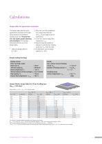
Calculations Design tables for approximate calculations The design tables allow for quick approximate calculation of the pipe laying distances and maximum heating circuit size. They do however not replace proper planning and calculation of the project. Instructions for the use of the design tables: 1. Select the design table for ϑi = 20°C 2. Select the row of the predefined max. design heat flow density qdes of your project (not for bathrooms!) 3. In this row, select a design flow temperature uV,des 4. Read the required installation distance Vz and the max. heating circuit size AFmax from the...
Open the catalog to page 5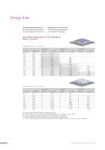
Design data The design tables below allow for the fast approximate calculation of the pipe spacing and the maximum heating circuit size. They do how ever not replace proper planning and calculation of the project. Uponor Minitec design tables for 15 mm levelling layer (∆p max. = 250 mbar) 32.6 94.7 5 8.70 5 7.00 32.2 90.0 5 9.15 5 7.45 5 5.20 31.3 80.0 5 10.15 5 8.45 5 6.30 30.9 70.0 5 11.25 5 9.55 5 7.50 29.7 60.0 5 12.55 5 10.80 5 8.75 29.2 55.0 5 13.25 5 11.50 5 9.45 28.8 50.0 5 14.05 5 12.25 5 10.15 27.9 40.0 5 14.50 5 14.05 5 11.85 The values in the design tables are based on the following...
Open the catalog to page 6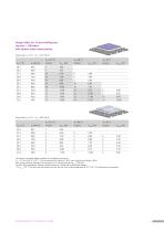
Design tables for 15 mm levelling layer (Δp max. = 100 mbar) with Uponor room control station Design table, ϑi = 20 °C , Rλ,B = 0.15 m2K/W 32.6 94.7 5 6.20 32.2 90.0 5 6.50 5 5.30 31.3 80.0 5 7.20 5 6.00 5 4.50 30.5 70.0 5 8.00 5 6.80 5 5.30 29.7 60.0 5 8.95 5 7.70 5 6.20 29.2 55.0 5 9.45 5 8.20 5 6.70 28.8 50.0 5 10.05 5 8.75 5 7.25 27.9 40.0 5 11.40 5 10.00 5 8.45 The values in the design tables are based on the following key figures: Rλ,ins = 0.75 m2K/W, ϑu = 20 °C, 130 mm concrete floor, spread = 3-30 K, max. heating circuit length = 80 m max. pressure drop per heating circuit including 2...
Open the catalog to page 7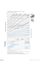
Design diagram heating/cooling Uponor Minitec with 15 mm levelling layer (sü = 4 mm with lü = 1.0 W/mK) Limit curve edge zone Vz 52) Limit curve comfort zone Vz 51) Specific cooling output qC [W/m2] Specific thermal output qH [W/m2] Limit curve valid for ϑi20 °C and ϑF, max 29 °C or ϑi 24 °C and ϑF, max 33 °C Limit curve valid for ϑi 20 °C and ϑF, max 35 °C Note: According to DIN EN 1264 are baths, showers and toilets not included. The limit curves must not be exceeded. The design supply water temperature must maximum be: ϑV, des = ∆ϑH, g + ϑi + 2.5 K ∆ϑH, g is found by the limit curve for the...
Open the catalog to page 8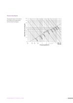
Pressure drop diagram 400 The pressure losses in the Uponor PE-Xa pipes can be determined with the aid of the diagram . Mass flow rate m in [kg/h] UPONOR MINITEC TECHNICAL GUIDE [mbar/m] [kPa/m]
Open the catalog to page 9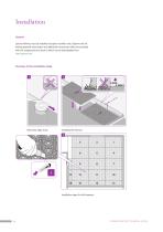
Installation General Uponor Minitec must be installed by expert installers only. Observe the following assembly instructions and additional instructions which are provided with the components and tools or which can be downloaded from www.uponor.com Overview of the installation steps Mounting edge strips Installing foil element 3 Installation steps for foil elements UPONOR MINITEC TECHNICAL GUIDE
Open the catalog to page 10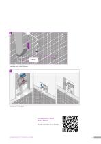
Installing pipes in foil elements Connecting PE-Xa pipes Get to know more about Uponor Minitec This QR code leads you to the film: UPONOR MINITEC TECHNICAL GUIDE
Open the catalog to page 11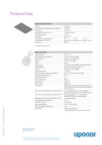
Technical data Uponor Minitec foil element Material Polystyrene Max. traffic load (including levelling compound) 5,0 kN/m2 Pipe spacing Vz 5, 10, 15 Foil element dimensions (l x w) 1,120 mm x 720 mm Total element height 12 mm System type Wet system* Volumetric share of levelling layer Vz 5 Vz 10 Vz 15 (at layer thickness 15 mm) approx. 12.4 l/m2 approx. 13.2 l/m2 approx. 13.5 l/m2 DIN reg. no. 7F170-F * on existing load distribution layer Production: Uponor AB, EL, Virsbo; Sweden Uponor PE-Xa pipe Pipe dimensions 9.9 x 1.1 mm SDR (Standard Dimension Ratio) Value 9 (acc. EN ISO 15875) S (Pipe...
Open the catalog to page 12All Uponor catalogs and technical brochures
 Uponor Minitec
3 Pages
 Uponor Smatrix
72 Pages
 Your feel-good connection
12 Pages

- Radiator
- Contemporary radiator
- Wall-mounted radiator
- Metal radiator
- Hot water radiator
- Vertical radiator
- Rectangular radiator
- Panel insulation
- Thermal insulation
- Industrial heat pump
- White radiator
- Synthetic insulation
- Residential heat pump
- Air source heat pump
- Industrial thermostat
- Wall insulation
- Outdoor heat pump
- High-performance insulation
- White thermostat