VD

VD
The Swirl Diffuser Type VD is designed for optimal ventilation in spaces with varying thermal loads, suitable for both cooling and heating. It features adjustable air pattern control blades for horizontal, angled, and vertical discharge, making it ideal for industrial and comfort conditioning applications. It can be installed in spaces with floor-to-ceiling heights of 3.8 meters or more, such as workshops and conference rooms, and is effective with supply air temperature differentials between -10K to +15K.
Construction and Materials
The diffuser is constructed with an aluminium face plate and a plenum box made of galvanized sheet steel. It includes adjustable air control blades that can be manually or electrically operated. Optional features include a protection grid for sports halls. The standard finish is natural anodised, with other color options available.
Installation and Weight
The VD diffusers can be installed flush with the ceiling or freely suspended. Installation requires the face to be 300 mm below a continuous closed ceiling for full angled discharge. The weight varies by size, with the VD-0 model ranging from 4 kg to 17 kg.
Technical and Acoustic Data
Technical specifications include supply air volume, spacing between diffusers, and effective free area. Acoustic data provides sound power levels and pressure drop information, with corrections for different configurations. The diffuser's sound power level is adjustable to meet specific requirements.
Aerodynamic Data
The document provides detailed aerodynamic data for different sizes and configurations, including maximum supply air penetration and core velocity at the wall. It includes examples for calculating sound power levels and air velocity in the occupied zone.
Order Details
Ordering information includes product codes and specifications for different configurations, such as diffuser face, plenum box, and actuator options. The document outlines the materials and finishes available for customization.
Catalog excerpts

Swirl Diffuser Type VD adjustable, for installation heights м 3.80 m TROX GmbH Heinrich-Trox-Platz D-47504 Neukirchen-Vluyn
Open the catalog to page 1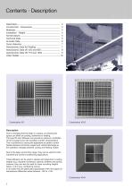
Contents · Description Description Construction · Dimensions Materials Installation · Weight Nomenclature Technical Data Acoustic Data Quick Selection Aerodynamic Data for Heating Aerodynamic Data VD 425 and 600 Aerodynamic Data VD 775 and 1050 Order Details Description Due to changing thermal loads in a space, air entering the space can either be cooling, isothermal or heating. The type VD swirl diffusers can provide an optimum ventilation of the occupied zone with excellent comfort characteristics. This is achieved by varying the adjustable air pattern control blades between horizontal, angled...
Open the catalog to page 2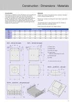
Construction · Dimensions · Materials Construction Depending on installation, all type VD diffusers can be supplied with top or side entry plenum boxes. The aluminium face plate is mounted on the plenum with visible screw fixings through the border. The face plate with control actuator and linkage comes as an integral assembly which is easily demountable from below. The air control blades can be adjusted either manually by using an electric actuator. For use in sports halls, a protection grid can be supplied as an optional extra. Diffuser face made of extruded aluminium sections. Standard finish...
Open the catalog to page 3
Installation · Weight Installation Swirl diffusers type VD can be installed flush with ceiling as well as freely suspended, due to their versatile characteristics. With a flush installation in open raster ceilings, the same flow conditions result as with a freely suspended situation. TROX-TDC can be used for the temperature-independent actuation of the heating or cooling mode. Protection grid-S A continuous adjustment of the direction of air flow can be made using an electrical actuator; see diffuser arrangement, figure 1. Installation of the face 300 mm below a continuous closed ceiling is required...
Open the catalog to page 4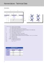
Nomenclature · Technical Data Nomenclature L · V in l/s or in m3/h: Supply air volume per diffuser A in m: Spacing between two diffusers in m: Distance between diffuser face and occupied zone in m/s: Time average air velocity between two diffusers at distance H1 from diffuser face in m: Distance from diffuser centre to wall + H1 in m/s: Time average air velocity at wall in m: Max. penetration of supply air when heating in K: Temperature difference between supply air and room air in K: Temperature difference between core and room at distance L = A/2 + H1 or L to the wall in m2: Effective free...
Open the catalog to page 5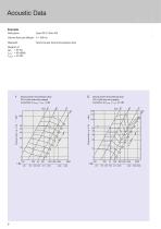
Data given: Type VD-V; Size 425 Volume flow per diffuser: V = 300 l/s Required: Sound power level and pressure drop 1 Sound power and pressure drop 2 Sound power and pressure drop VD-H (with side entry spigot) VD-V (with top entry spigot) Correction to LwNC = L„A -4 dB Correction to L^c = L„A -4.5 dB
Open the catalog to page 6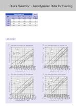
Quick Selection · Aerodynamic Data for Heating Quick Selection Max. supply air penetration vertical discharge Max. supply air penetration 60°- discharge angle Max. supply air penetration 75°- discharge angle Max. supply air penetration 45°- discharge angle
Open the catalog to page 7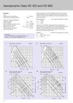
Aerodynamic Data VD 425 and VD 600 Resulting sound power level of 53 dB(A) is lower than the required value of 55 dB(A). For the calculation of the noise level in the room, correction for the number of diffusers and the room absorption must also be determined. Example Given: Supply air volume per diffuser Vertical duct connection, size 425 Supply air temperature difference: horizontal, cooling vertical, heating Max. permissible sound power level Spacing between diffusers Distance to wall = A/2 Freely suspended installation with top entry spigot Hence the warm airstream penetrates into the occupied...
Open the catalog to page 8
Aerodynamic Data VD 775 and VD 1050 Diagram 8, Page 8: Max. core velocity at the wall, cooling Diagrams are valid for cooling, horizontal discharge and freely suspended installation. Supply temperature difference: isothermal to – 10 K Operation in warm air mode, see page 7 L = A/2 + H1 L = 1.50 + 4.20 = 5.70 m ƒL = 0.21 m/s ͬt L/ͬt Z = 0.065 ͬt L = – 8 · 0.065 = – 0.52 K Result: On the basis of the given data and complying with the required limiting values the selection of VD-V size 425 is appropriate. Correction: For flush installation in continuous ceiling vH1, vL Max. core velocity at the...
Open the catalog to page 9
Order Details Square swirl diffuser with adjustable blades, suitable for swirling horizontal air discharge. By means of the adjustment of the diagonally disposed blade arrays, angled or vertical discharge can also be achieved. It is thus suitable for use at ceiling heights ≥ 3.8 m, particularly in the case of variation in supply air temperature differential Diffuser face made of extruded aluminium profiles, as standard natural anodised finish E6-C-0, alternatively with powder coat colour finish to RAL … . As VD-0 but with plenum box, suspension points and side entry circular spigot. Collar made...
Open the catalog to page 10All TROX catalogs and technical brochures
 Retrofit kits
6 Pages
 X-GRILLE Cover
18 Pages
 QUICK SELECTION GUIDE 2019 - 2
804 Pages
 QUICK SELECTION GUIDE 2019 - 1
530 Pages
 ATVC-100
8 Pages
 X-CUBE Compact
12 Pages
 X-CUBE RUN AROUND COIL SYSTEM
10 Pages
 Air-water systems
307 Pages
 ARR
ARR2 Pages
 WT · WL · EL
8 Pages
 VMRK
VMRK4 Pages
 VFR
VFR8 Pages
 Tunnel dampers
20 Pages
 FKS-EU
20 Pages
 CAK
CAK6 Pages
 Type ST · XT
8 Pages
 Type ARK · ARK1
8 Pages
 Type NL
8 Pages
 Type JZ · JNE · JZ-L · JZD-G
20 Pages
 Type FSL-B-ZAB
4 Pages
 Type PKV
7 Pages
 Type BID
8 Pages
 Type QLI
8 Pages
 TVJ-Easy/TVT-Easy
12 Pages
 LVC
LVC9 Pages
 RM-O-3-D
7 Pages
 RM-O-VS-D
7 Pages
 FK-EU
FK-EU56 Pages
 EK-01
EK-0114 Pages
 XSA
XSA12 Pages
 MSA
MSA12 Pages
 SCHOOLAIR-V
12 Pages
 SCHOOLAIR-B
12 Pages
 FSL-B-SEK
4 Pages
 DID632
20 Pages
 DID300B
12 Pages
 DID312
16 Pages
 AGW
AGW24 Pages
 AGS
AGS24 Pages
 DLQ-1...4-AK
13 Pages
 DQ/ADQ
9 Pages
 DLQ/ADLQ
10 Pages
 DLK-Fb
4 Pages
 QSH · ISH
8 Pages
 DLQL
DLQL12 Pages
 X-CUBE
16 Pages
 FV-K90
12 Pages
 TVR-Ex _ TES/TEF
7 Pages
 AK-Ex
AK-Ex5 Pages
 JZ-RS
JZ-RS5 Pages
 FKRS-EU
28 Pages
 Multileaf Dampers
8 Pages
 Star Climate
16 Pages
 X-GRILLE-Basic
4 Pages
 X-GRILLE-Basic
3 Pages
 Jet nozzles TJN
3 Pages
 ARCHITECTURE NEEDS TO BREATHE
16 Pages
 SD
SD10 Pages
 AIRNAMIC
12 Pages
 XARTO
XARTO12 Pages
 X-CUBE COMPACT
10 Pages


Archived catalogs
 Product Summary
7 Pages
 Displacement Flow Diffusers
32 Pages
 Quick selection guide
48 Pages
 The art of handling air
80 Pages
 Air-water systems Design manual
60 Pages
 Slot Diffuser
11 Pages
 Swirl Diffusers
17 Pages
 Grilles/Linear Grilles
24 Pages
 Passive Chilled Beams
7 Pages
 Swirl Diffusers Type FDE
6 Pages
 Swirl Diffuser Type VDW
20 Pages


- Ventilation grill
- Metal ventilation grill
- Rectangular ventilation grill
- Industrial air diffuser
- Aluminum ventilation grill
- Square ventilation grill
- Ceiling-mounted air diffuser
- Air handling unit
- Circular displacement air diffuser
- Square air diffuser
- Commercial air handling unit
- Ventilation damper
- Air filter
- Linear air diffuser
- Adjustable ventilation grill
- Metal ventilation damper
- Industrial air handling unit
- Slot air diffuser
- Linear ventilation grill
- Industrial jet nozzle