Slot Diffuser

Slot Diffuser
Catalog excerpts

Slot Diffuser Type VSD15 with 15 mm wide diffuser face 2/1/EN/4 TROX GmbH Telephone +49/28 45/2 02-0 Telefax +49/28 45/2 02-2 65 Heinrich-Trox-Platz e-mail [email protected] D-47504 Neukirchen-Vluyn www.troxtechnik.com
Open the catalog to page 1
Contents 2 Air Diffuser Discharge Characteristics (horizontal) 2 Description 3 Air Diffuser Discharge Characteristics (alternating) 3 Construction · Dimensions 4 Materials 4 Installation · Assembly 5 Air discharge horizontal, right Air discharge horizontal, left Nomenclature 7 Acoustic Data 7 Spectral Data 7 Aerodynamic Data 8 Order Details 11
Open the catalog to page 2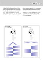
3 Description The recommended volume flow range is 8 to 25 l/s/m with a supply air temperature difference of up to ± 10 K. Because of their stable discharge characteristics, slot diffusers are suitable for use in systems with constant or variable volume air flows. The direction of air discharge can be adapted to the room conditions required. The air control blades are set as specified on the order. If the discharge direction has to be subsequently changed, this can easily be done by rotating the air control blades on site. The type VSD15 slot diffuser is ideal for use where suspended ceiling...
Open the catalog to page 3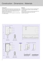
Construction · Dimensions · Materials 4 Construction The diffuser is supplied with the rear-mounted plenum box, which, if required, can be fitted with internal acoustic lining. The plenum has circular side entry spigot into which can, if required, be fitted volume control damper which can be adjusted from the diffuser face. The integral border, Z0, can be supplied for constructions A, F and D versions. Materials The diffuser face consists of aluminium extruded section. The visible surfaces of VSD15 are black (RAL 9005), powder coated. Visible surfaces of VSD15-Z0 natural anodised (E6-C-0). The...
Open the catalog to page 4
5 Installation · Assembly Fig. 1 Slot diffusers of type VSD15 are also suitable for mounting onto the sides of light troffers. The method of fixing and components required must be agreed. All necessary provisions/components will then be supplied by Trox, i.e. inserts, clamping angles etc. Fig. 4 shows an example with clamping angle and threaded insert. Fig. 2 Standard installation of slot diffusers using 4 suspension brackets fitted to the plenum box. Fig. 3 When slot diffusers are to be installed in panelled ceilings with external radius R 10 mm, they can be mounted up to 7 mm above the ceiling...
Open the catalog to page 5
Installation · Assembly 6 Fig. 7 The air flow rate can be adjusted from the diffuser face. The air control blade under the spigot should be rotated until the damper can be adjusted by a screwdriver or rod (max. 3.5 mm, approx. 100 mm long). The control blade can then be reset. Fig. 5 When slot diffusers are fitted in a linear format, connecting pins are used to align the front face. The connecting pins (2 per section) are first inserted into one section and then pushed halfway into the other section. Fig. 6 For an airtight seal on the first and last diffuser in a linear format, an end seal must...
Open the catalog to page 6
7 Nomenclature · Acoustic Data · Spectral Data Nomenclature V . in l/s · m: Volume flow per unit length V . in m3/h · m: Volume flow per unit length V . t in l/s: Total volume flow V . t in m3/h: Total volume flow A in m: Spacing between two diffusers H1 in m: Distance between ceiling and occupied zone H1 max in m: Max. penetration depth when heating L in m: Distance from diffuser L = A/2 + H1 or L = X + H1 v– H1 in m/s: Time average air velocity between two diffusers at distance H1 from the ceiling v– L in m/s: Time average air velocity at the wall at distance L veff in m/s: Effective jet velocity...
Open the catalog to page 7
Aerodynamic Data Air discharge: horizontal one direction 8 Example Data given: VSD15 Slot length L1 = 1000 mm Total volume flow V . t = 15 l/s Required: Octave band sound power level for regenerated noise LW 2 Air velocity between two diffusers and at the wall 3 Temperature Quotient Diffuser Layout Diagram 1: Sound power level and pressure drop LWA = 24 dB(A) pt = 18 Pa Effective jet velocity veff: veff= = = 3.75 m/s V . t seff · L1 · 1000 15 0.004 · 1 · 1000 Effective jet velocity V . t in l/s vt eff= = [m/s] V . t seff · L1 · 1000 V . t in m3/h seff = 0.004 m L1 = length of slot diffuser in...
Open the catalog to page 8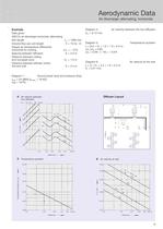
9 Aerodynamic Data Air discharge: alternating, horizontal Example Data given: VSD15; air discharge horizontal, alternating Slot length L1 = 1000 mm Volume flow per unit length . V = 15 l/s · m Supply air temperature differential horizontal for cooling tZ = – 10 K Spacing between diffusers A = 2.0 m Distance between ceiling and occupied zone H1 = 1.0 m Distance between diffuser centre line and wall X = 2.4 m Diagram 1: Sound power level and pressure drop LWA = 24 dB(A) (LWNC = 18 NC) pt = 18 Pa Diagram 4: Air velocity between the two diffusers v– H1 = 0.12 m/s Diagram 5: Temperature quotient L...
Open the catalog to page 9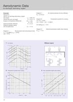
Aerodynamic Data Air discharge: alternating, angled 10 Example Data given: VSD15; air discharge alternating, angled Slot length L1 = 1000 mm Volume flow per unit length . V = 15 l/s · m Supply air temperature differential tZ = – 8 K or + 8 K Spacing between diffusers A = 2.4 m Distance between ceiling and occupied zone H1 = 1.2 m Diagram 1: Sound power level and pressure drop LWA = 24 dB(A) (LWNC = 18 NC) pt = 18 Pa Diagram 7: Air velocity between the two diffusers v– H1 = 0.19 m/s Diagram 8: Temperature quotient for cooling tH1/tZ = 0.042 tH1 = 0.042 · (– 8) = – 0.336 K for heating tz = + 8...
Open the catalog to page 10
11 0 Standard finish VSD15 black RAL 9005 VSD15-Z0 E6-C-0 P1 Powder-coated to RAL 9006 (GE 30%)2) other colours to RAL … (GE 70%)2) Note! Black air control blades standard. If required state “Air control blades white“ (similar RAL 9010). Order Details Order Code VSD15 -A-M- Z0 - L 900 600 700 800 900 1000 1100 1200 1300 1400 1500 L1 (mm) / / / Plenum box A Plenum box with lining D Face section F Volume control damper M1) Integral border Z0 Spigot with lip seal L1) 1) Only for construction with spigot 2) GE = gloss level 0 Not used State colour HL Horizontal left HR Horizontal right WH Alternating...
Open the catalog to page 11All TROX catalogs and technical brochures
 Retrofit kits
6 Pages
 X-GRILLE Cover
18 Pages
 QUICK SELECTION GUIDE 2019 - 2
804 Pages
 QUICK SELECTION GUIDE 2019 - 1
530 Pages
 ATVC-100
8 Pages
 X-CUBE Compact
12 Pages
 X-CUBE RUN AROUND COIL SYSTEM
10 Pages
 Air-water systems
307 Pages
 ARR
ARR2 Pages
 WT · WL · EL
8 Pages
 VMRK
VMRK4 Pages
 VFR
VFR8 Pages
 Tunnel dampers
20 Pages
 FKS-EU
20 Pages
 CAK
CAK6 Pages
 Type ST · XT
8 Pages
 Type ARK · ARK1
8 Pages
 Type NL
8 Pages
 Type JZ · JNE · JZ-L · JZD-G
20 Pages
 Type FSL-B-ZAB
4 Pages
 Type PKV
7 Pages
 Type BID
8 Pages
 Type QLI
8 Pages
 TVJ-Easy/TVT-Easy
12 Pages
 LVC
LVC9 Pages
 RM-O-3-D
7 Pages
 RM-O-VS-D
7 Pages
 FK-EU
FK-EU56 Pages
 EK-01
EK-0114 Pages
 XSA
XSA12 Pages
 MSA
MSA12 Pages
 SCHOOLAIR-V
12 Pages
 SCHOOLAIR-B
12 Pages
 FSL-B-SEK
4 Pages
 DID632
20 Pages
 DID300B
12 Pages
 DID312
16 Pages
 AGW
AGW24 Pages
 AGS
AGS24 Pages
 DLQ-1...4-AK
13 Pages
 DQ/ADQ
9 Pages
 DLQ/ADLQ
10 Pages
 DLK-Fb
4 Pages
 VD
VD10 Pages
 QSH · ISH
8 Pages
 DLQL
DLQL12 Pages
 X-CUBE
16 Pages
 FV-K90
12 Pages
 TVR-Ex _ TES/TEF
7 Pages
 AK-Ex
AK-Ex5 Pages
 JZ-RS
JZ-RS5 Pages
 FKRS-EU
28 Pages
 Multileaf Dampers
8 Pages
 Star Climate
16 Pages
 X-GRILLE-Basic
4 Pages
 X-GRILLE-Basic
3 Pages
 Jet nozzles TJN
3 Pages
 ARCHITECTURE NEEDS TO BREATHE
16 Pages
 SD
SD10 Pages
 AIRNAMIC
12 Pages
 XARTO
XARTO12 Pages
 X-CUBE COMPACT
10 Pages


Archived catalogs
 Product Summary
7 Pages
 Displacement Flow Diffusers
32 Pages
 Quick selection guide
48 Pages
 The art of handling air
80 Pages
 Air-water systems Design manual
60 Pages
 Swirl Diffusers
17 Pages
 Grilles/Linear Grilles
24 Pages
 Passive Chilled Beams
7 Pages
 Swirl Diffusers Type FDE
6 Pages
 Swirl Diffuser Type VDW
20 Pages


- Ventilation grill
- Metal ventilation grill
- Rectangular ventilation grill
- Aluminum ventilation grill
- Square ventilation grill
- Ceiling-mounted air diffuser
- Air handling unit
- Circular displacement air diffuser
- Square air diffuser
- Commercial air handling unit
- Ventilation damper
- Air filter
- Linear air diffuser
- Adjustable ventilation grill
- Metal ventilation damper
- Industrial air handling unit
- Slot air diffuser
- Linear ventilation grill
- Industrial jet nozzle