FKS-EU

FKS-EU
The document provides comprehensive technical specifications and installation guidelines for FKS-EU fire dampers, focusing on their design, functionality, and integration into building management systems. It covers the LON-WA1/B2 series and FKS-EU models, detailing control systems, sound power levels, and installation procedures for various wall types.
FKS-EU fire dampers are designed to automatically close in case of fire, preventing the spread of fire and smoke. They comply with EN 1366-2 and EN 15650 standards and can be installed in various wall types. The LON-WA1/B2 series controls up to two dampers with options for 24 V AC and 230 V AC supply voltages, using a microprocessor for data transfer compatible with LonMark standards.
Proper installation and adherence to national guidelines are crucial. Regular testing every six months is recommended, extendable to one year after two successful tests. Fire dampers should be included in the regular cleaning schedule of the ventilation system.
The dampers feature a rectangular construction with a rigid frame, available in various sizes. They include a fusible link or spring return actuator for release at specific temperatures (72°C or 95°C). The casing is made of galvanized or stainless steel, with powder coating options.
Accessories include installation blocks, cover plates, cover grilles, and flexible connectors, facilitating easy installation and ensuring functionality in different wall types. Limit switches and spring return actuators are available for remote control and monitoring.
Fire dampers can be installed in solid walls, ceiling slabs, lightweight partition walls, and fire walls. Installation must comply with federal state laws and recognized codes of practice. Flexible connectors are recommended to prevent load imposition during a fire.
The performance class depends on the application and installation type. Dampers allow airflow in either direction and have a large free cross-sectional area, resulting in low differential pressure. They are classified according to EN 13501-3.
Sound power levels are based on ISO 5135 standards, with calculations for different damper widths and air velocities. Example calculations are provided for determining differential pressure, sound power levels, and resistance coefficients.
Extension pieces are recommended for walls exceeding certain thicknesses. Guidelines ensure proper installation and compliance with fire resistance standards.
Order specifications for different configurations of FKS-EU fire dampers are included, highlighting features such as fusible links, powder coating, and spring return actuators.
The casing is made of galvanized sheet steel, the damper blade from special insulating material, and the damper blade shaft from stainless steel. Plain bearings are made of plastic.
The order code system allows customization based on type, construction, country of destination, nominal size, and accessories. Options include powder-coated or stainless steel casings, coated damper blades, and fusible links for warm air ventilation systems.
Various construction variants and accessories are available, including installation blocks and cover plates. A design program on the website provides more detailed information on different construction variants, attachments, and accessories.
Catalog excerpts

Fire dampers Type FKS-EU tested to EN 1366-2 according to Declaration of Performance DoP / FKS-EU / DE / 2013 / 001
Open the catalog to page 1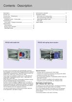
Contents · Description Description__________________________________ Correct use__________________________________ Construction · Dimensions_______________________ Accessories 1: Installation block · Cover plate__________________ Accessories 2: Cover grille · Flexible connectors________________ Attachments: Limit switches_______________________________ Spring return actuator_________________________ TROXNETCOM_____________________________ FKS-EU with fusible link In case of a fire, fire dampers shut automatically to prevent the propagation of fire and smoke through ductwork to adjacent designated...
Open the catalog to page 2
Correct use To ensure complete functioning of the fire damper it is essential to read the operating and installation manual and to comply with it. In addition, the national guidelines must be complied with. The general guidelines of DIN 31051 and EN 13306 are also applicable. The functional reliability of fire dampers must be tested at least every six months. If two consecutive tests are successful, the next test can be conducted one year later. In general, it is sufficient to release and re-open the damper blade; for fire dampers with spring return actuator this can be done by remote control....
Open the catalog to page 3
Construction · Dimensions Characteristics – Classified according to EN 13501-3 – For classes of performance see the table on page 3 – Combustible ventilation ducting may be connected directly – Airflow in either direction – Large free cross sectional area, hence low differential pressure – Release temperature 72 °C or 95 °C (for use in warm air ventilation systems) Approved installation positions for horizontal ducts Release mechanism Construction features – Rectangular construction, rigid frame – Connecting flanges on both ends, suitable for duct connection with System 30 flanges – Closed blade...
Open the catalog to page 4
Construction · Dimensions The construction variants with stainless steel or powder-coated casing meet even more critical requirements for corrosion protection. They are also available with a coated damper blade. Detailed listing on request. – Casing in galvanised sheet steel, with powder coating RAL 7001 (1), or in stainless steel 1.4301 (2) – Damper blade made of special insulation material – Damper blade coated in RAL7001 – Damper blade shaft in stainless steel – Plastic plain bearings Construction variant 1 Casing Galvanised Powder-coated Stainless steel Galvanised Powder-coated Stainless...
Open the catalog to page 5
Installation block · Cover plate Installation block FKS-EU fire dampers with installation block are required for installation without perimeter mortar infill (dry mortarless installation). Fire damper and installation block are assembled at the factory and form a unit. The unit is installed without a mortar-mix by simply inserting it into the prepared installation opening. In case of a fire the foaming seal closes the remaining gap. Installation block Cover plate Cover plate A cover plate simplifies the installation with perimeter mortar infill (wet installation). It can be screw fixed to a solid...
Open the catalog to page 6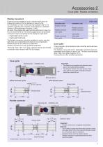
Cover grille · Flexible connectors Flexible connectors Ducting must be installed in such a manner that it does not impose any loads on the fire damper in case of a fire. For information on how to limit such loads please refer to the guideline regarding fire protection requirements on ventilation systems (Lüftungsanlagen-Richtlinie, LüAR). As ducts may expand and walls become deformed in case of a fire, we recommend for the following applications using flexible connectors when connecting the fire damper to rigid ducts: – in lightweight partition walls – in lightweight shaft walls The flexible...
Open the catalog to page 7
Attachments Limit switches FKS-EU with fusible link Order code Standard construction Limit switches with volt-free contacts enable the damper blade position indication. Relays or indicator lights for fire alarm systems can be used up to the maximum switch rating. One limit switch each is required for damper blade positions OPEN and CLOSED. Fire dampers with a fusible link can be supplied with one or two limit switches; the switches can also be fitted later. Standard construction with limit switch for damper blade position CLOSED Standard construction with limit switch for damper blade position...
Open the catalog to page 8
Attachments Spring return actuator FKS-EU with spring return actuator Order code Operation of the fire damper with a spring return actuator allows remote control and/or release by a suitable smoke detector. If the supply voltage fails, or with thermoelectric release, the damper closes (power off to close). Fire dampers with spring return actuator can be functionally checked OPEN/CLOSED/ OPEN. The actuator includes two limit switches. The connecting cables of the BLF24-T-ST TR are fitted with plugs. This ensures quick and easy connection to the TROX AS-i bus system. A conversion kit is available...
Open the catalog to page 9
Attachments TROXNETCOM FKS-EU with spring return actuator and TROXNETCOM Order code The fire dampers with spring return actuator BLF24-T-ST TR and the modules shown here as attachments form a functional unit ready for operation by an automatic fire damper controller. The components are factory-assembled and wired. Only the bus line and the supply voltage (LON only) remain to be connected by others. The AS interface is a world-standard bus system according to EN 50295 and IEC 62026-2. It enables the integration of different components (modules) in a network regardless of the manufacturer and the...
Open the catalog to page 10
Aerodynamic selection Nomenclature Given data: FKS-EU fire damper B = 600 mm, H = 100 mm, vA = 5 m/s Required: Δpt, LWA, LWNC, LW for 250 Hz, ζ Result: Δpt = 16 Pa from diagram LWA = 36 dB(A) LWNC = 36 – 5 = 31 LW = 36 + 1.5 = 37.5 dB at 250 Hz from table 1 ζ = 1.08 B [mm] : Width H [mm] : Height vA [m/s] : Air velocity based on B × H Δpt [Pa] : Total differential pressure (duct installation) ζ : Resistance coefficient (fully ducted) LWA [dB(A)] : Sound power level of the air-regenerated noise in the duct LWNC : NC rating of the sound power level LWNC ≈ LWA - 5 L W [dB] : Octave band sound power...
Open the catalog to page 11All TROX catalogs and technical brochures
 Retrofit kits
6 Pages
 X-GRILLE Cover
18 Pages
 QUICK SELECTION GUIDE 2019 - 2
804 Pages
 QUICK SELECTION GUIDE 2019 - 1
530 Pages
 ATVC-100
8 Pages
 X-CUBE Compact
12 Pages
 X-CUBE RUN AROUND COIL SYSTEM
10 Pages
 Air-water systems
307 Pages
 ARR
ARR2 Pages
 WT · WL · EL
8 Pages
 VMRK
VMRK4 Pages
 VFR
VFR8 Pages
 Tunnel dampers
20 Pages
 CAK
CAK6 Pages
 Type ST · XT
8 Pages
 Type ARK · ARK1
8 Pages
 Type NL
8 Pages
 Type JZ · JNE · JZ-L · JZD-G
20 Pages
 Type FSL-B-ZAB
4 Pages
 Type PKV
7 Pages
 Type BID
8 Pages
 Type QLI
8 Pages
 TVJ-Easy/TVT-Easy
12 Pages
 LVC
LVC9 Pages
 RM-O-3-D
7 Pages
 RM-O-VS-D
7 Pages
 FK-EU
FK-EU56 Pages
 EK-01
EK-0114 Pages
 XSA
XSA12 Pages
 MSA
MSA12 Pages
 SCHOOLAIR-V
12 Pages
 SCHOOLAIR-B
12 Pages
 FSL-B-SEK
4 Pages
 DID632
20 Pages
 DID300B
12 Pages
 DID312
16 Pages
 AGW
AGW24 Pages
 AGS
AGS24 Pages
 DLQ-1...4-AK
13 Pages
 DQ/ADQ
9 Pages
 DLQ/ADLQ
10 Pages
 DLK-Fb
4 Pages
 VD
VD10 Pages
 QSH · ISH
8 Pages
 DLQL
DLQL12 Pages
 X-CUBE
16 Pages
 FV-K90
12 Pages
 TVR-Ex _ TES/TEF
7 Pages
 AK-Ex
AK-Ex5 Pages
 JZ-RS
JZ-RS5 Pages
 FKRS-EU
28 Pages
 Multileaf Dampers
8 Pages
 Star Climate
16 Pages
 X-GRILLE-Basic
4 Pages
 X-GRILLE-Basic
3 Pages
 Jet nozzles TJN
3 Pages
 ARCHITECTURE NEEDS TO BREATHE
16 Pages
 SD
SD10 Pages
 AIRNAMIC
12 Pages
 XARTO
XARTO12 Pages
 X-CUBE COMPACT
10 Pages


Archived catalogs
 Product Summary
7 Pages
 Displacement Flow Diffusers
32 Pages
 Quick selection guide
48 Pages
 The art of handling air
80 Pages
 Air-water systems Design manual
60 Pages
 Slot Diffuser
11 Pages
 Swirl Diffusers
17 Pages
 Grilles/Linear Grilles
24 Pages
 Passive Chilled Beams
7 Pages
 Swirl Diffusers Type FDE
6 Pages
 Swirl Diffuser Type VDW
20 Pages


- Ventilation grill
- Metal ventilation grill
- Rectangular ventilation grill
- Industrial air diffuser
- Aluminum ventilation grill
- Square ventilation grill
- Ceiling-mounted air diffuser
- Air handling unit
- Circular displacement air diffuser
- Square air diffuser
- Commercial air handling unit
- Ventilation damper
- Air filter
- Linear air diffuser
- Adjustable ventilation grill
- Metal ventilation damper
- Industrial air handling unit
- Slot air diffuser
- Linear ventilation grill
- Industrial jet nozzle