EK-01

EK-01
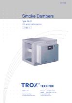
Smoke dampers Type EK-01 are designed for smoke removal in smoke control systems and can be installed in various wall and ceiling types, including concrete, masonry, and fire-rated ducts. They feature a reversible ON/OFF actuator and are classified under fire ratings EK90, EK60, or EK30, capable of withstanding temperatures up to 300°C or 600°C for 90, 60, or 30 minutes respectively.
The dampers are constructed using calcium silicate panels for the casing, isolating blade, and actuator casing, with bearings made from stainless steel or brass. Installation must allow for inspection, cleaning, and repair, with necessary inspection openings in the ducting.
Standard sizes range from 200/200 to 1500/800 mm in width/height, with casing lengths from 575 to 800 mm. They are suitable for solid walls, ceilings, plasterboard walls, lightweight partition walls, and fire-rated ducts, with specific installation requirements detailed in the document.
Installation can be performed in solid walls and ceilings, plasterboard walls, and lightweight partition walls with metal supports. Specific materials such as mineral wool and calcium silicate are required to ensure fire safety and compliance with DIN standards.
Smoke dampers require support in certain installations and must be serviced every six months, with annual servicing possible if no defects are found in consecutive checks. A service report must be maintained.
The document lists various actuator types and control modules, specifying their power requirements, protection systems, and auxiliary switch details. Ambient temperature limits for storage and operation are also provided.
Technical specifications include wiring connection diagrams and order details, ensuring proper installation and operation of the smoke dampers.
The document outlines the construction and specifications of smoke dampers, specifically type EK-01, used in smoke extract systems. The dampers are available in square or rectangular shapes and are constructed from galvanized sheet steel.
The dampers include profiled connecting flanges and cover grilles made from galvanized sheet steel, located on various ends as specified. Flexible connectors are available, non-combustible to DIN 4102, with temperature resistance options of 300°C, 600°C, and 1000°C.
Electrical systems must be designed for a functional duration of at least 30 minutes according to DIN 4102-12. The E30 cable is used, requiring strain relief and specific installation through the L90 casing.
Smoke dampers are operated by reversible ON/OFF actuators, with options for 1-wire or 2-wire control. The SEL 1.90 SLC actuator uses twisted pair technique and requires a BSLC communications device for operation.
The document provides a nomenclature for dimensions and flow velocity, with pressure drop values and correction factors for various blade widths. Example calculations are provided for determining total pressure drop based on given dimensions and flow velocity.
The document includes order codes and examples for specifying smoke dampers, including dimensions and ancillary options. Ancillaries and accessories are listed with corresponding codes for ordering.
The smoke dampers have a general building license from the German Institute for Building Technology. The document is published by TROX GmbH, with all rights reserved.
Catalog excerpts
Smoke Dampers Type EK-01 With general building approval Z-78.2-13 TROX GmbH Heinrich-Trox-Platz D-47504 Neukirchen-Vluyn
Open the catalog to page 1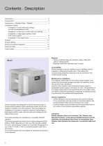
Contents · Description Description ______________________________________ ___ ___ __ Construction _____________________________________ __ ____ _ Applications · Standard Sizes · Weights ________________ _ __ Installation Details – Installation in solid walls and ceilings, as well as plasterboard walls ______________________ _ – Installation on the face of solid walls and ceilings ___ _ __ – Installation in lightweight partition walls with metal support _______________________________ _ – Installation in fire-rated ducts ______ _ ___________________ Support ________________________________________...
Open the catalog to page 2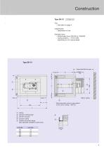
Use – See table on page 4 Classification – Dependent on use Standard sizes – Width/height from 200/200 to 1500/800 – Casing lengths L = 575 to 800, depending on the casing height * Approximate Minimum gap * Mindestabstand 50 Wand bzw.ceiling Wall or Decke * Recommended minimum gap relative to the wall or ceiling = 400 mm Casing Damper isolating blade ON/OFF actuator Actuator casing Profiled connection flange (also optionally available on both ends)
Open the catalog to page 3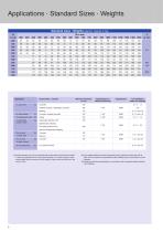
Applications • Standard Sizes • Weights Standard sizes • Weights (approx. figures in kg) - In fire rated ducts 3) e.g. calcium silicate - - - 9/4.1 and 4.2 1) Smoke dampers may only be combined with smoke extract ducts that are unable to exert any significant force on the smoke dampers or on walls, ceilings or other smoke extract ducts on account of their design or layout when they heat up in the 2) Only suitable flexible connectors (expansion joints) made from sheet steel with at least 100 mm expansion compensation (when installed) may be connected to smoke 3) Design and technical specifications...
Open the catalog to page 4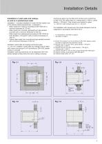
Installation Details Installation in solid walls and ceilings, as well as in plasterboard walls Installation – including installation in walls with the rotation axis of the damper blade perpendicular – is allowed in – Walls made from masonry according to DIN 1053 with a minimum thickness of 115 mm – Walls made from concrete, lightweight and gas-aerated concrete with a minimum thickness of 100 mm – Walls made from plasterboard according to DIN 18163 for bulk densities ≥ 0.6 kg/dm3 with a minimum thickness of 100 mm – Ceiling slabs made from concrete and gas-aerated concrete with a minimum thickness...
Open the catalog to page 5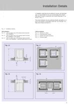
Installation Details In installation openings that are difficult to access, the perimeter gap “s” may be filled on one, two or three sides with mineral wool (item 2) used in conjunction with mortar filling (item 1), as shown in Fig. 1.7. The smoke dampers may be positioned directly alongside or on top of one another in accordance with Fig. 1.8, if the gap “s” is filled with mineral wool (item 2). Installation opening Wall installation Fig. 1.2 with the rotation axis of the damper blade horizontal (wet installation) Fig. 1.3 with the rotation axis of the damper blade horizontal (dry installation)...
Open the catalog to page 6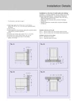
Installation Details Installation on the face of solid walls and ceilings Installation – including installation with the rotation axis of the damper blade perpendicular – is permitted on the face of – Walls made from masonry according to DIN 1053 with a minimum thickness of 115 mm – Walls made from concrete with a minimum thickness of 100 mm – Ceilings made from concrete with a minimum thickness of 100 mm For dimensions, see table on page 4 ቢ Steel angle, approx. 60 x 40 mm, min. 1.5 mm thick or approx. 80 x 40 mm, min. 3 mm thick when suspended below the ceiling ባ Quick-fix screw ቤ Dowel adequate...
Open the catalog to page 7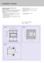
Installation Details Installation in lightweight partition walls with metal supports Installation in lightweight, assemblies and shaft walls with panel cladding on both sides and a metal support; this includes installation with the rotation axis of the damper blade perpendicular. – walls at least 100 mm thick clad with plasterboard panels F according to Table 48 in DIN 4102-4 – fire rated partition walls at least 100 mm thick made from calcium silicate panels – assembly and shaft walls with panel cladding on both sides at least 100 mm thick ቢ Partition wall / shaft wall ባ Packing, mineral wool,...
Open the catalog to page 8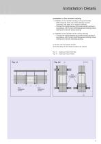
Installation Details Installation in fire-resistant ducting 1. Installation in fire-resistant ducting running horizontally – With horizontal ducts, the smoke damper must be supported; see page 10 for support methods. – Connect the smoke damper and smoke extract ducting in accordance with the test certificate/general building licence relating to the smoke extract ducting. 2. Installation in fire-resistant ducts running vertically – Connect the smoke damper and smoke extract ducting in accordance with the test certificate/general building licence relating to the smoke extracting ducting. ቢ Ducting...
Open the catalog to page 9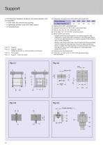
Support In the following installation situations, the smoke damper must be supported: – in solid walls with mineral wool packing – in lightweight partition walls with metal support – in horizontal ducts Support Support - detail A Ceiling fixing (with or without builders work fixing) Fixing plate Support - cross-bar detail ቢ Suspension (threaded rod), M8 to M20, galvanised steel Thread diameter Washer, M8 to M20, galvanised steel Hexagon head cap nut, M8 to M20, galvanised steel Spacer tube, dia. 30 x 33, galvanised steel Fixing plate, min. 10 mm thick, galvanised steel Metal builders work fixing...
Open the catalog to page 10
Product Range Accessories Construction with ON/OFF actuator type BE, made by Belimo Combined with - ON/OFF actuator with integrated limit switches Type BE24-12-ST U = AC 24 V, 50...60 Hz or. DC 24 V / opening P ≈ 12 W / in open position P ≈ 0.5 W / capacity 18 VA / protection system III / IP 54 / 100 % rated / running time < 60 s for 90° ˿ Auxiliary switch: 2 x EPU 6 (3) A, AC 250 V Ȟ Type BE230-12 U = AC 230 V, 50...60 Hz / opening P ≈ 8 W / in open position P ≈ 0.5 W / capacity 15 VA / protection system II / IP 54 / 100 % rated / running time < 60 s for 90° ˿ Auxiliary switch: 2 x EPU 6 (3)...
Open the catalog to page 11All TROX catalogs and technical brochures
 Retrofit kits
6 Pages
 X-GRILLE Cover
18 Pages
 QUICK SELECTION GUIDE 2019 - 2
804 Pages
 QUICK SELECTION GUIDE 2019 - 1
530 Pages
 ATVC-100
8 Pages
 X-CUBE Compact
12 Pages
 X-CUBE RUN AROUND COIL SYSTEM
10 Pages
 Air-water systems
307 Pages
 ARR
ARR2 Pages
 WT · WL · EL
8 Pages
 VMRK
VMRK4 Pages
 VFR
VFR8 Pages
 Tunnel dampers
20 Pages
 FKS-EU
20 Pages
 CAK
CAK6 Pages
 Type ST · XT
8 Pages
 Type ARK · ARK1
8 Pages
 Type NL
8 Pages
 Type JZ · JNE · JZ-L · JZD-G
20 Pages
 Type FSL-B-ZAB
4 Pages
 Type PKV
7 Pages
 Type BID
8 Pages
 Type QLI
8 Pages
 TVJ-Easy/TVT-Easy
12 Pages
 LVC
LVC9 Pages
 RM-O-3-D
7 Pages
 RM-O-VS-D
7 Pages
 FK-EU
FK-EU56 Pages
 XSA
XSA12 Pages
 MSA
MSA12 Pages
 SCHOOLAIR-V
12 Pages
 SCHOOLAIR-B
12 Pages
 FSL-B-SEK
4 Pages
 DID632
20 Pages
 DID300B
12 Pages
 DID312
16 Pages
 AGW
AGW24 Pages
 AGS
AGS24 Pages
 DLQ-1...4-AK
13 Pages
 DQ/ADQ
9 Pages
 DLQ/ADLQ
10 Pages
 DLK-Fb
4 Pages
 VD
VD10 Pages
 QSH · ISH
8 Pages
 DLQL
DLQL12 Pages
 X-CUBE
16 Pages
 FV-K90
12 Pages
 TVR-Ex _ TES/TEF
7 Pages
 AK-Ex
AK-Ex5 Pages
 JZ-RS
JZ-RS5 Pages
 FKRS-EU
28 Pages
 Multileaf Dampers
8 Pages
 Star Climate
16 Pages
 X-GRILLE-Basic
4 Pages
 X-GRILLE-Basic
3 Pages
 Jet nozzles TJN
3 Pages
 ARCHITECTURE NEEDS TO BREATHE
16 Pages
 SD
SD10 Pages
 AIRNAMIC
12 Pages
 XARTO
XARTO12 Pages
 X-CUBE COMPACT
10 Pages


Archived catalogs
 Product Summary
7 Pages
 Displacement Flow Diffusers
32 Pages
 Quick selection guide
48 Pages
 The art of handling air
80 Pages
 Air-water systems Design manual
60 Pages
 Slot Diffuser
11 Pages
 Swirl Diffusers
17 Pages
 Grilles/Linear Grilles
24 Pages
 Passive Chilled Beams
7 Pages
 Swirl Diffusers Type FDE
6 Pages
 Swirl Diffuser Type VDW
20 Pages


- Ventilation grill
- Metal ventilation grill
- Rectangular ventilation grill
- Industrial air diffuser
- Aluminum ventilation grill
- Square ventilation grill
- Ceiling-mounted air diffuser
- Air handling unit
- Circular displacement air diffuser
- Square air diffuser
- Commercial air handling unit
- Ventilation damper
- Air filter
- Linear air diffuser
- Adjustable ventilation grill
- Metal ventilation damper
- Industrial air handling unit
- Slot air diffuser
- Linear ventilation grill
- Industrial jet nozzle