DLQ-1...4-AK
1 /13Pages

DLQ-1...4-AK
1 /13Pages
Catalog excerpts
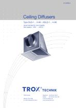
Ceiling Diffusers Type DLQ-1... 4-AK · ADLQ-1... 4-AK recommended for room heights from approx. 2.60 . . . 4.00 m TROX GmbH Heinrich-Trox-Platz D-47504 Neukirchen-Vluyn
Open the catalog to page 1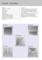
Contents · Description ____________________________________ 2 Description _______ _ Construction · Dimensions ____________________________ 3 ___________________________________________ 3 Materials Discharge directions ______________________________ 4 _________________________________ 5 Nomenclature _______ __________________________________ 5 Spectral-Data _______ _ Acoustic Data ________________________________________ 5 Aerodynamic Data _________________________________ 7 _ Aerodynamic Data DLQ/ADLQ 300 __________________ 8 __________________ 9 _ Aerodynamic Data DLQ/ADLQ 400 _ Aerodynamic...
Open the catalog to page 2
Construction · Dimensions · Materials Construction The face sections of the type DLQ and ADLQ consist of a peripheral border with fixed air control blades. The plenum box is supplied with a circular side entry spigot and an optional volume control damper which can be adjusted from the front face. The diffuser face is permanently rivetted to the plenum box. The diffuser face is made from formed sheet steel. The surface is pre-treated and powder coated white (RAL 9010). The plenum box is made from galvanised sheet steel. ADLQ Materials The diffuser face is made from extruded aluminium sections,...
Open the catalog to page 3
Discharge Directions Location of Connecting Spigot The diffuser face can be supplied in a 1 to 4 way discharge pattern, as required. The side entry spigot of the plenum box is located on side A as standard. If the customer requires it to be located on another side for architectural reasons, this must be indicated in the order code. (No indication need be given for the 4 way discharge pattern).
Open the catalog to page 4
Nomenclature · Spectral Data · Acoustic Data H1 Aeff ƒL ƒH1 Δpt in Pa: LWA in dB(A): : LWNC : LWNR : LpA, LpNC Volume flow per diffuser Volume flow per diffuser Spacing between two diffusers Horizontal plus vertical distance (X + H1) discharge to the wall in m: Distance between centre of diffusers and the wall in m: Critical distance from the diffuser at which the supply air flow drops from the ceiling when in the cooling mode (a function of ‡ and ΔtZ) Distance between ceiling and occupied zone Effective outlet area Time average air velocity at the wall Time average air velocity between two diffusers...
Open the catalog to page 5
Acoustic Data Example Data given: DLQ-4-AK (supply air), size 600 Volume flow per diffuser ‡ = 300 l/s Required: Octave band sound pressure level of regenerated noise LW Diagram 1: LWA = 35 dB(A) Δpt = 18 Pa Sound power level and pressure drop Octave band centre frequency in Hz Sound power level and pressure drop Type DLQ/ADLQ-1. . . 4-AK (supply air) Correction for Diagram 3: Damper setting Size 300 Blade angle Sound power level and pressure drop Type DLQ/ADLQ-1. . . 4-AK (extract air) Sound power level and pressure drop Type DLQ/ADLQ-2E-AK (supply air)
Open the catalog to page 6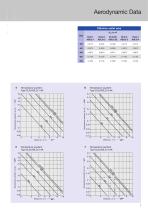
Aerodynamic Data Effective outlet area Aeff in m2 Size Temperature quotient Type DLQ/ADLQ-1-AK 0.8 Temperature quotient Type DLQ/ADLQ-3-AK 0.5 0.4 Temperature quotient ΔtL/ΔtZ Temperature quotient ΔtL/ΔtZ Temperature quotient Type DLQ/ADLQ-2-AK Temperature quotient Type DLQ/ADLQ-4-AK 0.5 0.4 Temperature quotient ΔtL/ΔtZ Temperature quotient ΔtL/ΔtZ
Open the catalog to page 7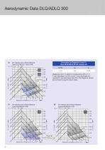
Aerodynamic Data DLQ/ADLQ 300 Correction for Diagrams 8 and 11: Type DLQ/ADLQ-2E-AK (supply air) Air velocity and critical distance Type DLQ/ADLQ-1 and 2-AK 1.0 1.2 Diagrams 8 and 11 apply to constructions with a 1 or 2 way discharge. For the corner 2 way discharge the opposed 2 way discharge data from the diagrams should be corrected using the above table. Recommended zones Spacing A or Distance L or X crit. in m Air velocity and critical distance Type DLQ/ADLQ-3-AK Spacing A or Distance L or X crit. in m Spacing A or Distance L or X crit. in m Recommended zones Recommended zones Air velocity...
Open the catalog to page 8
Aerodynamic Data DLQ/ADLQ 400 Air velocity and critical distance Type DLQ/ADLQ-1 and 2-AK 1.0 1.2 Recommended zones Air velocity and critical distance Type DLQ/ADLQ-3-AK 1.0 1.2 Air velocity and critical distance Type DLQ/ADLQ-4-AK 1.0 1.2 Spacing A or Distance L or X crit. in m Spacing A or Distance L or X crit. in m Spacing A or Distance L or X crit. in m
Open the catalog to page 9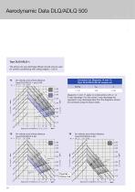
Aerodynamic Data DLQ/ADLQ 500 Type DLQ/ADLQ-1: The above one way discharge diffuser should only be used for comfort conditioning with ceiling heights > 3.20 m Correction for Diagrams 14 and 17: Type DLQ/ADLQ-2E-AK (supply air) Air velocity and critical distance Type DLQ/ADLQ-1 and 2-AK 1.0 1.2 Recommended zones Diagrams 14 and 17 apply to constructions with a 1 or 2 way discharge. For the corner 2 way discharge the opposed 2 way discharge data from the diagrams should be corrected using the above table. Recommended zones Air velocity and critical distance Type DLQ/ADLQ-3-AK 1.0 1.2 Air velocity...
Open the catalog to page 10
Aerodynamic Data DLQ/ADLQ 600 Example Data given: DLQ-4-AK, size 600 Volume flow per diffuser ‡ = 300 l/s Supply air temperature differential ΔtZ = – 6 K Spacing between two diffusers A = 6.20 m Distance between ceiling and occupied zone H1 = 1.2 m Distance between centre of diffuser and the wall X=4m Horizontal plus vertical distance discharge to the wall L = 5.2 m Diagram 19: Air velocity and critical ƒH1 = 0.12 m/s distance between two diffusers ƒL = 0.21 m/s at the wall X crit. = 4.9 m X < X crit. Consequently there is no risk of the air flow dropping from the ceiling prematurely. Diagram...
Open the catalog to page 11
Aerodynamic Data DLQ/ADLQ 625 Type DLQ/ADLQ-1: The above one way discharge diffuser should only be used for comfort conditioning with ceiling heights > 3.20 m Air velocity and critical distance Type DLQ/ADLQ-1 and 2-AK 1.0 1.2 Correction for Diagram 20: Type DLQ/ADLQ-2E-AK (supply air) Diagram 20 applies to constructions with a 1 or 2 way discharge. For the corner 2 way discharge the opposed 2 way discharge data from the diagrams should be corrected using the above table. Recommended zones Recommended zones Air velocity and critical distance Type DLQ/ADLQ-3-AK 1.0 1.2 Air velocity and critical...
Open the catalog to page 12All TROX catalogs and technical brochures
 Retrofit kits
6 Pages
 X-GRILLE Cover
18 Pages
 QUICK SELECTION GUIDE 2019 - 2
804 Pages
 QUICK SELECTION GUIDE 2019 - 1
530 Pages
 ATVC-100
8 Pages
 X-CUBE Compact
12 Pages
 X-CUBE RUN AROUND COIL SYSTEM
10 Pages
 Air-water systems
307 Pages
 ARR
ARR2 Pages
 WT · WL · EL
8 Pages
 VMRK
VMRK4 Pages
 VFR
VFR8 Pages
 Tunnel dampers
20 Pages
 FKS-EU
20 Pages
 CAK
CAK6 Pages
 Type ST · XT
8 Pages
 Type ARK · ARK1
8 Pages
 Type NL
8 Pages
 Type JZ · JNE · JZ-L · JZD-G
20 Pages
 Type FSL-B-ZAB
4 Pages
 Type PKV
7 Pages
 Type BID
8 Pages
 Type QLI
8 Pages
 TVJ-Easy/TVT-Easy
12 Pages
 LVC
LVC9 Pages
 RM-O-3-D
7 Pages
 RM-O-VS-D
7 Pages
 FK-EU
FK-EU56 Pages
 EK-01
EK-0114 Pages
 XSA
XSA12 Pages
 MSA
MSA12 Pages
 SCHOOLAIR-V
12 Pages
 SCHOOLAIR-B
12 Pages
 FSL-B-SEK
4 Pages
 DID632
20 Pages
 DID300B
12 Pages
 DID312
16 Pages
 AGW
AGW24 Pages
 AGS
AGS24 Pages
 DQ/ADQ
9 Pages
 DLQ/ADLQ
10 Pages
 DLK-Fb
4 Pages
 VD
VD10 Pages
 QSH · ISH
8 Pages
 DLQL
DLQL12 Pages
 X-CUBE
16 Pages
 FV-K90
12 Pages
 TVR-Ex _ TES/TEF
7 Pages
 AK-Ex
AK-Ex5 Pages
 JZ-RS
JZ-RS5 Pages
 FKRS-EU
28 Pages
 Multileaf Dampers
8 Pages
 Star Climate
16 Pages
 X-GRILLE-Basic
4 Pages
 X-GRILLE-Basic
3 Pages
 Jet nozzles TJN
3 Pages
 ARCHITECTURE NEEDS TO BREATHE
16 Pages
 SD
SD10 Pages
 AIRNAMIC
12 Pages
 XARTO
XARTO12 Pages
 X-CUBE COMPACT
10 Pages


Archived catalogs
 Product Summary
7 Pages
 Displacement Flow Diffusers
32 Pages
 Quick selection guide
48 Pages
 The art of handling air
80 Pages
 Air-water systems Design manual
60 Pages
 Slot Diffuser
11 Pages
 Swirl Diffusers
17 Pages
 Grilles/Linear Grilles
24 Pages
 Passive Chilled Beams
7 Pages
 Swirl Diffusers Type FDE
6 Pages
 Swirl Diffuser Type VDW
20 Pages


- Ventilation grill
- Metal ventilation grill
- Rectangular ventilation grill
- Industrial air diffuser
- Aluminum ventilation grill
- Square ventilation grill
- Ceiling-mounted air diffuser
- Air handling unit
- Circular displacement air diffuser
- Square air diffuser
- Commercial air handling unit
- Ventilation damper
- Air filter
- Linear air diffuser
- Adjustable ventilation grill
- Metal ventilation damper
- Industrial air handling unit
- Slot air diffuser
- Linear ventilation grill
- Industrial jet nozzle