DID312

DID312
Active chilled beams Type DID312 are designed for air-water systems to efficiently air condition rooms with high cooling loads. They combine the properties of ceiling diffusers with energy-efficient water-based cooling, making them suitable for buildings with low ceiling voids due to their low height construction.
The system supplies conditioned fresh air from a central plant to maintain indoor air quality, while providing additional cooling or heating through heat exchangers. The primary air is mixed with induced secondary air, which passes through heat exchangers before being discharged into the room.
The beams are constructed from galvanized sheet steel and aluminum, featuring a casing, face frame, and heat exchangers made of copper tubes and aluminum fins. They are available in various lengths and widths to fit different ceiling systems.
The system can handle fresh air flow rates from 5 to 70 l/s and is suitable for room heights from 2.6 to 4.0 meters. It includes options for supply-extract-air combinations with integral extract air casing.
Installation requires trained personnel and compliance with legal regulations. The beams are suspended from the ceiling using certified hanging systems, and connections can be rigid or flexible.
Regular cleaning of the diffuser and heat exchanger is necessary, following guidelines such as VDI 6022 for hygiene requirements.
The document provides detailed nomenclature for various parameters like air flow rates, cooling capacities, and temperature differences. A quick selection guide and example calculations are provided to assist in choosing the appropriate unit based on specific room requirements.
- High cooling capacity with low fresh air flow rates
- Options for two or four pipe systems
- Suitable for flush ceiling installation
- Certified under the Eurovent Certification Programme
Catalog excerpts
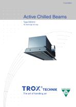
Active Chilled Beams Type DID312
Open the catalog to page 1
Contents · Description Description __________________________________ 2 Functional description __________________________ 3 Construction · Dimensions ______________________ 4 Supply-extract-air combination __________________ 5 Casing configurations Supply air __________________________________ 6 Supply-extract-air combination __________________ 7 Installation __________________________________ 8 Assembly____________________________________ 9 Nomenclature ________________________________10 Selection example ____________________________11 Quick selection ______________________________12 Water-side...
Open the catalog to page 2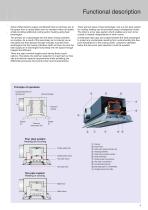
Functional description Active chilled beams supply conditioned fresh air (primary air) to the space from a central plant room to maintain indoor air quality whilst providing additional cooling and/or heating using heat exchangers. The primary air is discharged into the beam mixing chamber via nozzles. As a result of this secondary air is induced via an inlet grille and then passes through vertically mounted heat exchangers into the mixing chambers. Both air flows mix and the total supply air is discharged horizontally into the space through integral slot diffusers. There are eight nominal lengths...
Open the catalog to page 3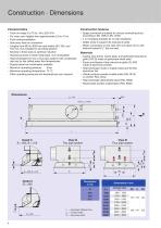
Construction · Dimensions Characteristics Construction features Fresh air range 5 to 70 l/s, 18 to 252 m³/h For clear room heights from approximately 2.6 to 4.0 m Flush ceiling installation Side entry fresh air connection Lengths from 893 to 3000 mm and widths 293, 300, and 312 mm, thus suitable for all ceiling systems Nozzles in three sizes to optimise induction Nozzles punched in sheet metal plate, non-combustible Heat exchangers for two or four pipe systems with condensate drip tray for low chilled water flow temperatures Supply-extract-air combination available Maximum operating pressure:...
Open the catalog to page 4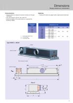
Supply-extract-air combination Characteristics – Integral extract air casing for removal of extract air through the ceiling – Flow rate range 5 to 50 l/s, 18 to 180 m³/h – Extract air spigot on the same side as or opposite the primary air spigot – Casing with extract air spigot made of galvanised sheet steel L = total length (diffuser face) LN = nominal length B = Face frame width Fresh (primary) air spigot Fresh (primary) air spigot
Open the catalog to page 5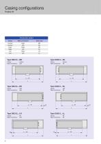
Casing configurations Supply air Centred Centred Right Right Left Left Construction variant Water connections Right Left Right Left Right Left Order code Type DID312...-MR Casing: Water connections: centred right Casing: Water connections: centred left Type DID312...-RR Casing: Water connections: Casing: Water connections: right right Casing: Water connections: right left left right Casing: Water connections: left left
Open the catalog to page 6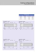
Casing configurations Supply-extract-air combination Right Right Left Left Casing: Water connections: left left Type DID312...-LL-AH Casing: Water connections: left left Casing: Water connections: Water connections Right Right Left Left Construction variant right right Casing: Water connections: 107 right right Front Rear Front Rear RR-AV RR-AH LL-AV LL-AH Order code
Open the catalog to page 7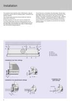
Installation The customer must install the active chilled beams, make all connections, and provide the hanging system, connection and sealing materials. Only trained expert personnel should install and make the appropriate connections. All legal regulations for site work must be complied with. The active chilled beam has four hanging brackets (six on nominal length 2100 and above) for suspending the unit from the ceiling slab using threaded rods, wires or metal hangers. Use only certified hanging systems. Casing Face frame Side entry spigot Hanging brackets Installation into T-bar ceilings The...
Open the catalog to page 8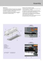
Assembly Maintenance As is the case with all diffusers that induce room air, depending on the cleanliness of the room air, deposits may accumulate on the surfaces of the diffuser. If required, clean the diffuser with commercial, non-aggressive cleaning agents. Clean the heat exchanger with an industrial vacuum cleaner. For maintenance, also see VDI 6022, Sheet 1 – “Hygiene Requirements on Ventilation Systems”. Removal of the induced air grille The heat exchangers are accessible when the induced air grille has been hinged down or removed. To hinge down the induced air grille on its long side by...
Open the catalog to page 9
∆tl ∆th1 ∆tPr ∆tW ∆tRWV ∆pt ∆pW tR tWVK tWRK tWVH tWRH tPr QWK QWH Qtot QPr VWK VWH VPr VPrN VExt vl vh1 LWA a l h₁ h x Temperature difference between room air and core at distance l = x +h₁ Temperature difference between room air and core at distance l = a ⁄ 2 + h₁ Temperature difference between room air and conditioned fresh air Temperature difference between water flow and return Temperature difference between room air and water flow Total differential pressure Water-side pressure differential Room temperature Water flow temperature – cooling Water return temperature – cooling Water flow temperature...
Open the catalog to page 10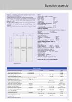
Selection example First step in selecting active chilled beams is based on the quick selection table (Page 12). Listed capacities are valid only for the reference values. Second step, if the operating values differ from the reference ones, corrections must be made using diagrams and tables pages 13 to 15. Our “Easy Product Finder” online design programme is also available on the Internet for easy and detailed design of our products. Following example shows the unit selection using this leaflet. 4.05 Given Flexible office, width 3 modules Room width: 4.05 m Room depth: 5m Room height: 3m Occupancy:...
Open the catalog to page 11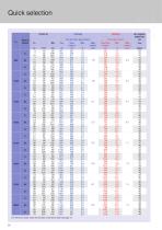
For reference values which are the basis of the above table see page 13
Open the catalog to page 12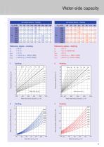
Reference values – Cooling tR tPr tWVK VWK VWK Water-side cooling capacity QWK in W Water flow rate VWK in l/h Reference values – Heating Water flow rate VWK Water-side pressure differential ∆pW in kPa Correction factors – Heating Water-side pressure differential ∆pW in kPa Correction factors – Cooling Water flow rate VWH 400 Water-side heating capacity QWH in W Water flow rate VWH in l/h
Open the catalog to page 13All TROX catalogs and technical brochures
 Retrofit kits
6 Pages
 X-GRILLE Cover
18 Pages
 QUICK SELECTION GUIDE 2019 - 2
804 Pages
 QUICK SELECTION GUIDE 2019 - 1
530 Pages
 ATVC-100
8 Pages
 X-CUBE Compact
12 Pages
 X-CUBE RUN AROUND COIL SYSTEM
10 Pages
 Air-water systems
307 Pages
 ARR
ARR2 Pages
 WT · WL · EL
8 Pages
 VMRK
VMRK4 Pages
 VFR
VFR8 Pages
 Tunnel dampers
20 Pages
 FKS-EU
20 Pages
 CAK
CAK6 Pages
 Type ST · XT
8 Pages
 Type ARK · ARK1
8 Pages
 Type NL
8 Pages
 Type JZ · JNE · JZ-L · JZD-G
20 Pages
 Type FSL-B-ZAB
4 Pages
 Type PKV
7 Pages
 Type BID
8 Pages
 Type QLI
8 Pages
 TVJ-Easy/TVT-Easy
12 Pages
 LVC
LVC9 Pages
 RM-O-3-D
7 Pages
 RM-O-VS-D
7 Pages
 FK-EU
FK-EU56 Pages
 EK-01
EK-0114 Pages
 XSA
XSA12 Pages
 MSA
MSA12 Pages
 SCHOOLAIR-V
12 Pages
 SCHOOLAIR-B
12 Pages
 FSL-B-SEK
4 Pages
 DID632
20 Pages
 DID300B
12 Pages
 AGW
AGW24 Pages
 AGS
AGS24 Pages
 DLQ-1...4-AK
13 Pages
 DQ/ADQ
9 Pages
 DLQ/ADLQ
10 Pages
 DLK-Fb
4 Pages
 VD
VD10 Pages
 QSH · ISH
8 Pages
 DLQL
DLQL12 Pages
 X-CUBE
16 Pages
 FV-K90
12 Pages
 TVR-Ex _ TES/TEF
7 Pages
 AK-Ex
AK-Ex5 Pages
 JZ-RS
JZ-RS5 Pages
 FKRS-EU
28 Pages
 Multileaf Dampers
8 Pages
 Star Climate
16 Pages
 X-GRILLE-Basic
4 Pages
 X-GRILLE-Basic
3 Pages
 Jet nozzles TJN
3 Pages
 ARCHITECTURE NEEDS TO BREATHE
16 Pages
 SD
SD10 Pages
 AIRNAMIC
12 Pages
 XARTO
XARTO12 Pages
 X-CUBE COMPACT
10 Pages


Archived catalogs
 Product Summary
7 Pages
 Displacement Flow Diffusers
32 Pages
 Quick selection guide
48 Pages
 The art of handling air
80 Pages
 Air-water systems Design manual
60 Pages
 Slot Diffuser
11 Pages
 Swirl Diffusers
17 Pages
 Grilles/Linear Grilles
24 Pages
 Passive Chilled Beams
7 Pages
 Swirl Diffusers Type FDE
6 Pages
 Swirl Diffuser Type VDW
20 Pages


- Ventilation grill
- Metal ventilation grill
- Rectangular ventilation grill
- Industrial air diffuser
- Aluminum ventilation grill
- Square ventilation grill
- Ceiling-mounted air diffuser
- Air handling unit
- Circular displacement air diffuser
- Square air diffuser
- Commercial air handling unit
- Ventilation damper
- Air filter
- Linear air diffuser
- Adjustable ventilation grill
- Metal ventilation damper
- Industrial air handling unit
- Slot air diffuser
- Linear ventilation grill
- Industrial jet nozzle