Active Chilled Beams Type DID600B

Active Chilled Beams Type DID600B
Catalog excerpts

T 2.4/3/EN/1 Active Chilled Beams Type DID600B
Open the catalog to page 1
Contents Description 2Construction 8Performance overview cooling 3Casing arrangements 9with 2-pipe and 4-pipe systemsPerformance overview ֖ heating 4Dimensions 5Assembly 10with 4-pipe systems Aerodynamic data 6Nomenclature 11Order details 12 > Caution!The cold water supply temperature must be selected such that it never falls below room dewpoint.Max. pressure: for 2-pipe and 4-pipe system 6 bar at 90C 7 bar at 20аC Other operating pressures available on request! The type DID600B chilled beams are particularly suitable for use in low ceiling void spaces because of their shallow construction....
Open the catalog to page 2
1a Supply air top entry connecting spigot > L > N 900 up to 1800 = 123 > 1b Supply air side entry connecting spigot L > N 2100 up to 3000 = ؘ 158 Top of casing (plenum) Discharge nozzles Casing Coil (pipe- 12 mm) Perforated plate induction grille Discharge slots Label chilled water (blue) Label warm water (red)Extract air top connecting spigot Extract air side connecting spigot > 10a Construction with top entry supply air spigot View Construction with top extract air spigot View > 380ظD 98 10a 1a 18 50 110 18143 593 593 Construction with side extract air spigot > 10b Construction with side entry...
Open the catalog to page 3
Arrangement of the top active plenumExtends over total length (standard)L > Arrangement of the top active plenum (plenum shorter than L 1 ) 900 80040435458893900 > leftL 1200 11004043545811931200 > N L > H L > L L > R L > 1 1500 14004043545814931500 1800 17004043545817931800 minmaxminmax 2100 20004043545820932100 900 8004325365810961500 2400 23004043545823932400 1200 11004325365813961800 2700 26004043545826932700 1500 14004325365816962100 3000 29004043545829933000 1800 17004325365819962400 2100 20004325365822962700 2400 23004325365825963000 V - L H - LV H - LH 2700 26004325335828963000 > Arrangement...
Open the catalog to page 5
Assembly Assembly The two long sides of the DID600B are each provided with two suspension holes or for L1 = 1500 4 holes are provided on each side. The assembly is installed on site using wire or metal hangers which must have the Building Authority certificate of approval. When the DID600B has been installed, 4 locking devices can be loosened with a screw driver (detail X) and the whole induction grille can be lowered down lengthways. The induction grille is supported by two safety cables. The coil is accessible when the induction grille is removed. The coil connections are on the outside of...
Open the catalog to page 6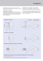
Ceiling panel/tile Grid(AW)*Support angle > 18 30 or 40 mm BL1R 593 >
Open the catalog to page 7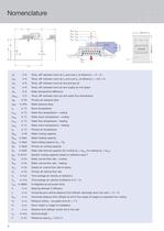
XA WH t WVH N WH t WRH LJ Pr L + 300 mm WK t WRK Pr t t Pr WK WVK L N 1 Top entryconnectionSide entryconnection LJ Pr Pr H t Pr DID600BF 5000 mm L ; âȆ t L H1 ; âȆ t H1 1,7 mH 1.7 m ges Zul L L raum room ǢȆ t > L in K:Temp. diff. between room air t > R and core t > L at distance L = X + H > 1 ∆ t > H1 in K:Temp. diff. between room air t > R and core t > H1 at distance L = A/2 + H > 1 ∆ t > Pr in K:Temp. diff. between room air and primary air ∆ t > Z in K:Temp. diff. between room air and supply air into space ∆ t > W in K:Water temperature difference ∆ t > RWV in K:Temp. diff. between room air and...
Open the catalog to page 8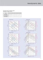
Aerodynamic data
Open the catalog to page 11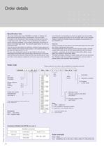
Order dtails
Open the catalog to page 12All TROX catalogs and technical brochures
 Retrofit kits
6 Pages
 X-GRILLE Cover
18 Pages
 QUICK SELECTION GUIDE 2019 - 2
804 Pages
 QUICK SELECTION GUIDE 2019 - 1
530 Pages
 ATVC-100
8 Pages
 X-CUBE Compact
12 Pages
 X-CUBE RUN AROUND COIL SYSTEM
10 Pages
 Air-water systems
307 Pages
 ARR
ARR2 Pages
 WT · WL · EL
8 Pages
 VMRK
VMRK4 Pages
 VFR
VFR8 Pages
 Tunnel dampers
20 Pages
 FKS-EU
20 Pages
 CAK
CAK6 Pages
 Type ST · XT
8 Pages
 Type ARK · ARK1
8 Pages
 Type NL
8 Pages
 Type JZ · JNE · JZ-L · JZD-G
20 Pages
 Type FSL-B-ZAB
4 Pages
 Type PKV
7 Pages
 Type BID
8 Pages
 Type QLI
8 Pages
 TVJ-Easy/TVT-Easy
12 Pages
 LVC
LVC9 Pages
 RM-O-3-D
7 Pages
 RM-O-VS-D
7 Pages
 FK-EU
FK-EU56 Pages
 EK-01
EK-0114 Pages
 XSA
XSA12 Pages
 MSA
MSA12 Pages
 SCHOOLAIR-V
12 Pages
 SCHOOLAIR-B
12 Pages
 FSL-B-SEK
4 Pages
 DID632
20 Pages
 DID300B
12 Pages
 DID312
16 Pages
 AGW
AGW24 Pages
 AGS
AGS24 Pages
 DLQ-1...4-AK
13 Pages
 DQ/ADQ
9 Pages
 DLQ/ADLQ
10 Pages
 DLK-Fb
4 Pages
 VD
VD10 Pages
 QSH · ISH
8 Pages
 DLQL
DLQL12 Pages
 X-CUBE
16 Pages
 FV-K90
12 Pages
 TVR-Ex _ TES/TEF
7 Pages
 AK-Ex
AK-Ex5 Pages
 JZ-RS
JZ-RS5 Pages
 FKRS-EU
28 Pages
 Multileaf Dampers
8 Pages
 Star Climate
16 Pages
 X-GRILLE-Basic
4 Pages
 X-GRILLE-Basic
3 Pages
 Jet nozzles TJN
3 Pages
 ARCHITECTURE NEEDS TO BREATHE
16 Pages
 SD
SD10 Pages
 AIRNAMIC
12 Pages
 XARTO
XARTO12 Pages
 X-CUBE COMPACT
10 Pages


Archived catalogs
 Product Summary
7 Pages
 Displacement Flow Diffusers
32 Pages
 Quick selection guide
48 Pages
 The art of handling air
80 Pages
 Air-water systems Design manual
60 Pages
 Slot Diffuser
11 Pages
 Swirl Diffusers
17 Pages
 Grilles/Linear Grilles
24 Pages
 Passive Chilled Beams
7 Pages
 Swirl Diffusers Type FDE
6 Pages
 Swirl Diffuser Type VDW
20 Pages

- Ventilation grill
- Metal ventilation grill
- Rectangular ventilation grill
- Industrial air diffuser
- Aluminum ventilation grill
- Square ventilation grill
- Ceiling-mounted air diffuser
- Air handling unit
- Circular displacement air diffuser
- Square air diffuser
- Commercial air handling unit
- Ventilation damper
- Air filter
- Linear air diffuser
- Adjustable ventilation grill
- Metal ventilation damper
- Industrial air handling unit
- Slot air diffuser
- Linear ventilation grill
- Industrial jet nozzle