
Catalog excerpts
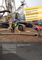
The construction of diaphragm walls by hydromill allows the construction of panels with max deviation from the vertical of about 0.2 - 0.5%, at depths beyond 200 m. With tiiis technology, it is possible soil layers and excavate diaphragm wails in bedrocks with compressive strength The hydromill also allows to correct any deviation from the vertical while excavating, in order cut competent. The special diaphragm wall construction sequence by hydromill and primary-secondary panels overlapping ensure higher chances of watertight joints than conventional grabs. With the hydromill technology it...
Open the catalog to page 3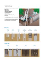
The diaphragm wall construction phases by hydromill • site preparation • construction of guide walls • pre-trench excavation • panel excavation • slurry de-sanding • installation of reinforcement cage The panels are divided into PRIMARY and SECONDARY The PRIMARY panels can be realized by either single or multiple bites, as shown in the scheme below. PRIMARY PANELS PHASE 1 PHASE 2 PHASE 3 PHASE 4 PHASE 5 PHASE 6 PRE-TRENCH 1st BITE 2nd BITE INTERMEDIATE BITE CAGE INSTALLATION CONCRETING SECONDARY PANELS PHASE 7 PHASE 8 PHASE 9 PHASE 10 PRE-EXCAVATION EXCAVATION CAGE INSTALLATION CONCRETING
Open the catalog to page 4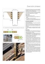
Execution phases (pane/ thickness) SV = concrete overcut in the primary panel when excavating the secondary panel Secondary panel width Site preparation and guide wall construction operations are similar to the ones usually carried out when excavating a diaphragm wall by conventional grab. The work area must have bearing capacity of suitable for the construction equipment. The guide walls can be schematically realized as shown in the figure. Guide walls Guide walls are needed to ensure: • a guide for the excavation and proper alignment of • a support to the vertical loads generated by the...
Open the catalog to page 5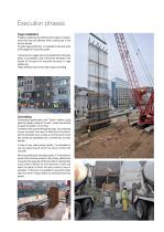
Execution phases Cage installation Property positioning the reinforcement cage is crucial to avoid that they are affected when cutting part of the primary panels. To guide cage positioning, it is possible to use stop ends at the edges of the primary panel. In the event two cages have to be positioned in the same panel, it is possible to use a temporary template in the middle of the panel for improved accuracy in cage These elements will be removed during concreting. Concreting is performed by the "Tremie" method, using pipes of a length of about 2 m each, joined one another to reach the...
Open the catalog to page 6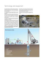
The hydromill system consists of three main pieces of equipment the milling unit, the carrier supporting it and the mud processing plant to treat the mud extracted The milling unit is made up of a steel frame onto which two independent counter-rotating milling drums are Milling drums with different torques and dimensions can be used to better suit the geometrical requirements. The milling unit is cable-suspended to the supporting crane's boom and controlled by means of a precision hydraulic system. The hydromill is progressively lowered into the trench; it excavates and crushes the soil or...
Open the catalog to page 8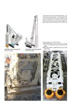
The hydraulic motors for the submerged elements - two milling dmms and mud pumps - can be powered either by an external hydraulic power pack mounted on the carrier, or directly by the hydraulic carrier engine. Both hydraulic hoses and reverse circulation drilling mud pipes shall follow the movement of the milling unit. a) SOILMEC 'Tiger1 series hydromill b) SOILMEC 'Cougar1 series hydromill (hose wheel design) Two configurations are usually adopted: a) with hose drums (for hydraulic, electric and cuttings suction hoses) fixed onto a frame mounted on the b)with hose wheels suspended at the...
Open the catalog to page 9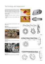
The hydromill always rests at the bottom of the trench and crushes the material across the whole front section. Different types of teeth can be assembled to the milling drums. Tooth configuration can be adapted to soil nature. Generally speaking, the teeth have either one of the following shapes: • flat, with carbide plate, suitable for mixed soil • conical, with carbide round insert, suitable for rocky Teeth can be arranged on the milling drums in three different ways: Suitable for coarse and cohesive soils, alluvial soils with small-sized boulders and medium-soft rocks. Suitable for...
Open the catalog to page 10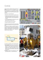
In the construction of diaphragm walls by hydromill, the DMS plays a crucial role for the management, control and monitoring of the production process. Indeed the operator has to manage and control a number of parameters to ensure deep excavations are properly Among them, worth mentioning are: • milling drum rotation speed and applied torque; • hydraulic back-pressure in the hydraulic motors to compensate the pressure exerted from the outside to the inside of the trench, which varies depending on • crowd force/load applied to the milling drums to ensure proper penetration inside the trench;...
Open the catalog to page 12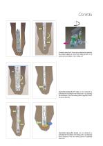
Correction along the X-X axis can be obtained by adjusting the rotation speed of one of the milling drums, or by opening the side flaps of the milling unit. Correction along the Y-Y axis can be obtained by activating the front flaps of the milling unit or by adjusting the inclination of the two milling drums together and in Correction along the Z-axis can be obtained by activating the front flaps of the milling unit or by adjusting the inclination of the two milling drums in opposite
Open the catalog to page 13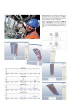
Depth Course Besides standard data processing and printing out of depth-based excavation trend diagrams, the DMS in the PC version also allows to display panel cross-sections at specific depths, with panel overlap area. With an additional option to the software, the DMS can create a 3D rendering of the project to assess the quality of joints between panels and total deviation of each panel, by combining displacements along X-Y-Z
Open the catalog to page 15
World leader in ground engineering, Trevi has been working for more than 50 years throughout the world, strengthening its ability to provide solutions to any ground engineering issues. Trevi works in the field of special foundation, soil consolidation, dam remedial works, tunnel construction and consolidation, marine works, rehabilitation and cleanup of contaminated sites and construction of underground automatic multi-storey car parks. Trevi is committed to continuous innovation and search for solutions to complex problems of civil engineering worldwide. Experimenting cutting-edge...
Open the catalog to page 16All Trevi Group catalogs and technical brochures
-
Dynamic Compaction (DC)
12 Pages
-
TECHNOLOGIES - JET GROUTING
12 Pages
-
TECHNOLOGY - INJECTIONS
12 Pages
-
TECHNOLOGIES - DISCREPILE
8 Pages
-
TECHNOLOGIES - GROUND FREEZING
12 Pages
-
GENERAL CATALOGUE
6 Pages


