- Catalogs
- Tensar International
- Tensar Uniaxial Brochure
Tensar Uniaxial Brochure

Tensar Uniaxial Brochure
This guide provides a comprehensive overview of Tensar Uniaxial Geogrids, used in reinforced soil structures like bridge abutments and retaining walls. It focuses on deriving design strength by considering factors such as strength, durability, and soil interaction.
The design strength is based on long-term strength factors, including rupture and limiting strain. A formula is provided to calculate design strength, emphasizing the impact of time and temperature on polymer behavior.
Tensar geogrids are made from durable polymers, with tensile strength affected by temperature and strain rate. Quality control follows BS EN ISO 10319:1996, and creep tests predict long-term performance.
Creep tests provide data for isochronous load-strain curves, helping determine load limits for minimal post-construction strain.
Field trials assess construction impacts, with safety factors for installation damage. Additives like carbon black mitigate environmental exposure, ensuring durability.
Tensar geogrids resist chemical and biological degradation, suitable for aggressive environments and resistant to stress cracking.
The guide offers insights into Tensar Uniaxial Geogrids, emphasizing material behavior understanding for long-term stability and safety.
Geogrids connect using a polymer bodkin joint bar, maintaining full strength without reduction factors, suitable for various applications.
Soil stabilization involves mechanical interaction through sliding or pullout, defined by friction and pullout tests, crucial for design.
Tensar geogrids are accredited by international agencies, affirming their suitability for reinforced soil structures.
Made from HDPE through a patented process, enhancing strength and stiffness.
Long-term design strength is calculated using factors for manufacturing, installation, environmental effects, and load, with an example for Tensar 80RE.
Specifications include polymer type, junction strength, and long-term creep rupture strength, with factors for manufacturing and environmental conditions.
Catalog excerpts

The Properties and Performance of Tensar Uniaxial Geogrids The essential guide to the long-term properties of Tensar Uniaxial Geogrids for use in designing: Bridge abutments Retaining walls Steep embankment slopes Slip repairs
Open the catalog to page 1
Tensar design consultation or workshop www.tensar-international.com 2 How to use this guide This is your essential guide to the long-term properties of Tensar uniaxial polymer geogrids for use in reinforced soil structures. Polymers are not simple elastic materials. Their load-strain behaviour is also affected by time and temperature. These effects are product specific and they lead to a unique design strength for each project and set of conditions. There is a simple conceptual formula: Design strength = Long-term strength factors Long term strength may be defined in terms of rupture (ultimate...
Open the catalog to page 2
3 Figure 1: Effect of temperature and strain rate on tensile strength of polymer geogrid. Tensile strength All polymer based products are visco-elastic. Their strength and stiffness are affected both by temperature and by rate or duration of loading, as shown on Figure 1. Therefore, it is important that standard methods of tensile testing are used, so that temperature and strain rate are defined. For Tensar uniaxial geogrids, quality control (QC) tensile testing is carried out using the method given in International Standard BS EN ISO 10319:1996. This is a wide width method with specimen width...
Open the catalog to page 3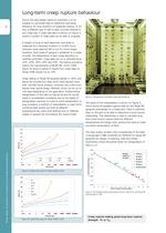
Tensar design consultation or workshop www.tensar-international.com 4 Long-term creep rupture behaviour Due to the visco-elastic nature of polymers, it is not possible to use tensile tests to determine load-strain behaviour for long durations of sustained loading. To do this, a different type of test is used, normally referred to as a creep test. A creep laboratory is shown on Figure 3, where a number of creep tests can be seen in progress. A weight is hung on each specimen, and strain is measured for a standard duration of 10,000 hours. However, many tests are left to run for much longer durations....
Open the catalog to page 4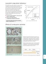
5 The long-term deformation behaviour of polymer geogrid is assessed by constructing isochronous load-strain curves. Isochronous data is taken directly from the straintime curves shown on Figures 4a and 4b by reading off the data from the plotted lines at fixed time values. Figure 6 shows isochronous load-strain curves determined in this way for Tensar 120RE at 20ºC, for both 1 month and 120 years duration. For serviceability limit state design to BS8006:1995, isochronous curves are used to find the geogrid load which limits postconstruction strain to: 1% over the period between 1 month and 120...
Open the catalog to page 5
Tensar design consultation or workshop www.tensar-international.com 6 The trial procedure is illustrated in Figure 9. A layer of fill is placed both below and above the geogrid. The upper layer is compacted to three levels of compaction and then carefully excavated so that the geogrid can be recovered. The geogrid is examined to check for damage. Based on this examination, test specimens are selected from the areas which exhibit the greatest damage. Wide width tensile tests are carried out on these specimens, and the results are compared to tests carried out on control samples. Typical tensile...
Open the catalog to page 6
7 External exposure In most applications geogrid will be buried in soil, so that it will be protected from external environmental conditions. However, at a number of stages during its use, it is likely to be exposed, certainly during handling and installation on site, but also possibly in service. Exposure might be for a relatively long duration, and it is therefore important that the geogrid material is well protected. Some construction specifications and approval certificates provide protection by limiting the allowable duration of exposure, but these requirements are difficult to control and...
Open the catalog to page 7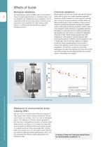
Tensar design consultation or workshop www.tensar-international.com 8 Effects of burial Chemical resistance Buried geogrid will come into contact with soil and ground water, both of which can contain potentially aggressive substances. HDPE is resistant to a wide range of chemicals, and it is inert to all aqueous solutions of acids, alkalis and salts normally found in soils. In addition, it has no known solvents at ambient temperatures. Because of its stability under a wide range of chemical conditions, HDPE is used in many situations where hazardous or aggressive chemicals are present, for example:...
Open the catalog to page 8
9 Connecting Tensar Uniaxial Geogrids Tensar uniaxial geogrids may be easily connected together on site in the direction of loading using a polymer bodkin joint bar. The bodkin joint provides a full strength connection, so that no reduction factor or partial safety factor is required in designs which incorporate the joint. This versatile connector can be used to: connect main reinforcement to short starters (as shown in Figure 14) use short off-cuts to minimise waste form wrap-around connections in slope construction The unique form and properties of Tensar uniaxial geogrids make them ideal for...
Open the catalog to page 9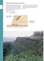
Tensar design consultation or workshop www.tensar-international.com 10 Mechanical interaction with soil Stabilising soil masses using reinforced soil techniques requires mechanical interaction between geogrid and soil. Interaction can take the form of sliding or pullout. Examples of failure mechanisms which mobilise these two forms of interaction are shown on Figure 16. Sliding between geogrid and soil is defined by a simple coefficient of friction given by: friction coefficient = átanö’ where ö’ = friction angle of the soil á = interaction factor The interaction factor (á) is therefore a reduction...
Open the catalog to page 10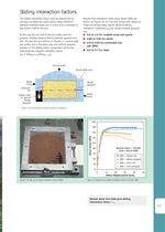
11 Figure 17b: Set up for shear box test on Tensar 80RE. Figure 18: Results from sliding interaction tests on Tensar 40RE. Figure 17a: Cross section of shear box test to measure ás. Sliding interaction factors The sliding interaction factor may be determined by carrying out shear box tests using a large (300mm) specially modified shear box in which grid is clamped to the bottom half of the box. In this way the top half of the box slides over the geogrid, thereby creating sliding between geogrid and soil. The test set-up is shown on Figure 17. Control tests are carried out in the same way, but...
Open the catalog to page 11All Tensar International catalogs and technical brochures
 Tensar HX
1 Page
 Road-Technology
12 Pages
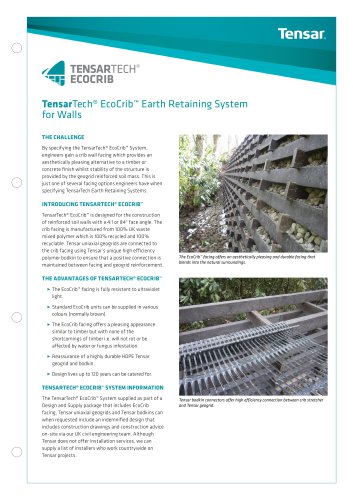
 TensarTech® EcoCrib™
2 Pages
 TensarTech® SlopeLoc™
2 Pages
 TensarTech™ slopeloc™
3 Pages
 Tensar GlasstexPatch 880
2 Pages
 Tensar Mining Brochure
4 Pages
 Tensar Railway Brochure
12 Pages
 Tensar Sub ballast Stabilisation
12 Pages
 Tensar TriAx Geogrid Brochure
12 Pages
 TensarTech Stratum
6 Pages
 Tensar Railways
12 Pages
 Tensar Oil and Gas Brochure
5 Pages
 TENSAR GEOPIER FOUNDATIONS
8 Pages
 Tensar Erosion Control
12 Pages
 Tensar_TriAx_TX
12 Pages
 Foundations over Piles
6 Pages
 Basal Reinforcement
6 Pages
 Tensar_GlasstexPatch_880
2 Pages
 TensarTech_TW3
6 Pages
 TensarTech_TW1
6 Pages
 Tensartech_TR2_System
4 Pages
 TensarTech_NaturalGreen
6 Pages
 TensarTech_GreenSlope
6 Pages
 Tensartech_Geocell_brochure
6 Pages
 Wind_Energy_Brochure
6 Pages
 Tensar_Oil_and_gas_brochure
5 Pages


Archived catalogs
 Tensar Erosion Control Brochure
12 Pages
 Tensar Wind Energy Brochure
6 Pages
 Tensar Ballast Stabilisation
2 Pages
 TensarTech Ares
2 Pages
 TensarTech Stratum Brochure
6 Pages
 Tensartech TW1 Wall Brochure
6 Pages
 TensarTech Plateau Brochure
6 Pages
 Tensar Architects Brochure
11 Pages
 Tensar General Brochure
20 Pages
 Tensar Mining Brochure
8 Pages
 Tensar_Erosion_Control
12 Pages
 Asphalt Reinforcement
10 Pages
 Tensar General Brochure
20 Pages
 Tensar_Mining_Brochure
5 Pages
 Tensartech_TW3
6 Pages
 Tensar_Sales_Leafle
3 Pages
 New_Architects
11 Pages
 Tensartech_Green Slope
6 Pages
 Tensar Basal Reinforcement
8 Pages
 Tensar Erosion Brochure
2 Pages
 TriAx brochure 2010
12 Pages
 Tensar Railways Brochure
12 Pages


- Industrial geotextile
- Concrete retaining wall
- Modular retaining wall
- Reinforcement geogrid
- Geocomposite
- Prefab retaining wall
- Plastic geotextile
- Reinforced concrete retaining wall
- Industrial gabion
- Woven geotextile
- Reinforcement geotextile
- Polypropylene geocomposite
- Stone look retaining wall
- Foundation geogrid
- Stone retaining wall
- Ground stabilization geogrid
- Public work geogrid
- Bridge construction retaining wall