

wpc

wpc
- EC Conformity: The WPC 5 controller adheres to EC directives for low voltage and electromagnetic compatibility.
- General Instructions: The manual provides crucial safety, installation, and operation guidelines, intended for trained specialists only.
- Explanation of Symbols: Symbols highlight potential dangers like electric shock or equipment damage.
- Warranty: A two-year warranty is offered, excluding damages from misuse or unauthorized modifications.
- Specifications: Operates at 230VAC with 2VA power consumption, supports multiple sensor inputs, and functions within specific temperature and humidity ranges.
- Functionality: Designed for efficient heat pump control with a graphical display, extensive settings, and error detection.
- Scope of Supply: Includes the controller, installation accessories, and optional temperature sensors.
- Disposal: Must be disposed of according to RoHS directives, not with household waste.
- Hydraulic Variants: Supports various system configurations, requiring additional safety components as needed.
- Wall Installation: Detailed steps for mounting the controller on a wall in dry areas.
- Electrical Connection: Safe connection instructions, emphasizing separation of low and high voltage cables.
- Display and Input: Features a user-friendly interface with a menu-driven system for easy navigation.
- Commissioning: Guidance on initial setup and configuration for optimal performance.
- Error Messages: List of potential error messages and troubleshooting steps.
- Maintenance: Regular procedures to ensure longevity and reliability.
- Anti-seizing and Frost Protection: Features to protect the heat pump and heating circuits from damage.
- Program Selection and Sensor Calibration: Options for customizing operation and ensuring accurate sensor readings.
Details on electrical connections for various hydraulic systems, specifying terminal blocks for neutral and protective conductors. Mains voltage is 230VAC 50-60Hz, with low voltage connections in the left-hand terminal compartment. Specific terminals are designated for different components like heating circuit pumps and compressors. Sensor connections include options for RS485 interfaces.
Temperature sensor cables must be routed separately from mains voltage cables. The system uses Pt1000 sensors for accurate control, with cables extendable up to 30m. Proper placement is crucial for accuracy.
Requires a 2-strand twisted-pair cable, routed separately from mains voltage cables. A special circuit board is needed, and proper polarity must be ensured. Jumpers are required for the first and last units in a sequence.
The controller can display external error conditions via sensor input terminals. Short circuits can stop or shut down the heat pump, with errors displayed on the screen.
Features a display with text and graphics for easy operation. LEDs indicate different modes and errors. Four keys are used for input, with functions varying based on the situation. The menu structure allows navigation through settings and functions.
Includes options for displaying current temperature values, controlling system functions, setting operating times, and configuring parameters. A commissioning help feature guides initial setup, with manual configuration available.
Displays measurement values based on the selected program and connected sensors. The statistics menu provides function control and long-term monitoring, including operating hours and heat output.
Allows setting the current time, date, and operating times for heating circuits and hot water. Specific time ranges can be set for different days, with options for increased temperatures during low-rate periods.
- Low-Rate Time Period: Select based on usage patterns and utility low-rate periods.
- Domestic Hot Water (Menu 3.7): Set a time range for each day to charge the water tank to a higher temperature for Legionella protection. Default is off.
- Operating Modes (Menu 4): Modes include Automatic, On, Off, Continuous Day/Night, Reference, and Manual. Default is Automatic.
- Settings (Menu 5): Includes Summer/Winter changeover, minimum flow temperature, heating characteristic slope, day/night correction, comfort temperature boost, and low-rate period boost.
- Anti-Seizing Protection (Menu 6.1): Activates daily or weekly to prevent pump/valve sticking.
- Frost Protection (Menu 6.2): Activates if glycol return temperature drops below set value.
- Anti-Legionella (Menu 6.5): Heats water tank to higher temperature at set times. Default is off.
- Program Selection (Menu 7.1): Select hydraulic variant for application. Default is 1.
- Heat Quantity (Menu 7.2): Simple heat metering function available.
- Glycol Type: Options are ethylene or propylene, with ethylene as the default.
- Glycol Portion: Adjustable from 0% to 60%, default is 40%.
- Flow Rate: Ranges from 10 to 20000 l/h, default is 3000 l/h.
- Sensor Calibration: Allows manual compensation for temperature deviations, adjustable in 0.5°C steps.
- Commissioning: Guided setup for initial commissioning, only to be performed by specialists.
- Factory Settings: Resets all settings to default, requiring recommissioning.
- Expansions: Additional options available if expansion modules are installed.
- Runtime: Compressor remains on for a set time after heat demand, default is 10 minutes.
- Delay: Glycol and other pumps activate before the compressor, default delay is 20 seconds.
- Overrun: Glycol pump continues running after compressor shutdown, default is 20 seconds.
- Idle Time: Compressor remains off for a set time after operation, default is 10 minutes.
- Heating Circuit Pump: Can be set to operate based on outdoor temperature or flow, default is outdoor temperature.
Secures the controller against unintended changes, with certain menus remaining accessible.
Language selection available during initial commissioning, varies by device design.
Used for remote diagnosis, should be recorded during errors for specialist consultation.
- Error Messages: Indicate sensor issues, frost protection, or temperature limits.
- Fuse Replacement: Instructions for replacing a defective fuse.
- Maintenance: Annual checks recommended, including date/time verification and parameter optimization.
- Remote Adjuster: Allows temperature adjustments from living space.
- Cost Savings: Controller can optimize storage tank charging during low-rate periods.
SOREL GmbH Mikroelektronik, contact details provided for further assistance.
Catalog excerpts

Heat pump controller WPC 5 Installation and operating instructions -1 H5 Eli Wrmepumpen Conlroller Read carefully before installation, commissioning and operation
Open the catalog to page 1
pj~|Safety instructions [T] 1.1 EC dclaration of conformity By affixing the CE mark to the unit the manufacturer dclares that the WPC5 conforms to the following relevant safety regulations: - EC low voltage directive 73/23/EEC, as amended by 93/68/EEC - EC electromagnetic compatibility directive 89/336/EEC version 92/31/EEC version 93/68/EEC Conformity has been verified and the corresponding documentation and the EC declaration of conformity are kept on file by the manufacturer. 1.2 General instructions It is essential that you read this! These installation and operating instructions contain...
Open the catalog to page 3
1 Safety instructions 1 1.4 Changes to the unit Changes to the unit can compromise the safety and function of the unit or the entire system. Danger - Changes, additions to or conversion of the unit are not permitted without written permission from the manufacturer - It is likewise forbidden to install additional components that have not been tested together with the unit - If it becomes clear that safe operation of the unit is no longer possible, for example because of damage to the housing, then turn the controller off immediately - Any parts of the unit or accessories that are not in perfect...
Open the catalog to page 4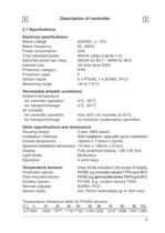
2 Description of controller 2 2.1 Spcifications Electrical spcifications: Mains voltage Mains frequency Power consumption Total switched power Switched power per relay Internal fuse Protection category Protection class Sensor inputs Measuring range 230VAC +/- 10% 50...60Hz 2VA 460VA (relay outputs 1-4) 460VA for AC1 / 185W for AC3 2A slow-blow 250V IP40 II 5 x Pt1000, 1 x SOREL RT21 -40 to 110°C Permissible ambient conditions: Ambient temperature for controller operation for transport/storage Air humidity for controller operation for transport/storage 0°C...40°C 0°C...60°C max. 85% rel. humidity...
Open the catalog to page 5
2 Description of controller 2 2.2 About the controller The Heat pump controller WPC 5 facilittes efficient use and function control of your heat pump and heating system. The device is impressive most of all for its functionality and simple, almost self-explanatory operation. For each step in the input process the individual entry keys are assigned to appropriate functions and explained. The controller menu contains headwords for the measured values and settings, as well as help texts or clearly-structured graphics. The WPC 5 can be used as a heat pump controller for the various system variants...
Open the catalog to page 6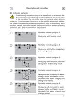
2 Description of controller 2 2.5 Hydraulic variants The following illustrations should be viewed only as schematic dia-grams showing the respective hydraulic Systems, and do not claim T Caution to be complete. The controller does not replace safety devices under any circumstances. Depending on the specific application, additio-nal system components and safety components may be mandatory, such as check valves, non-return valves, safety temperature limiters, scalding protectors, etc., and must therefore be provided. 2 Hydraulic variant / program 1 Heat pump with heating circuit Hydraulic variant...
Open the catalog to page 7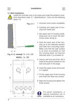
3 Installation 3 3.1 Wall installation Install the controller only in dry areas and under the ambient conditions described under 2.1 ̈́Specifications". Carry out the following T Caution steps 1-8. Fig. 3.1.1 1. Unscrew cover screw completely 2. Carefully pull upper part of hou-sing from lower part. 3. Set upper part of housing aside, being sure not to touch the electronics when doing so. 4. Hold the lower part of the hou-sing up to the selected position and mark the 3 mounting holes. Make sure that the wall surface is as even as possible so that the housing does not become distorted when it is...
Open the catalog to page 8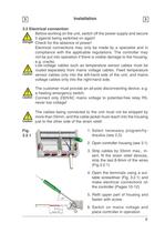
3 Installation 3 3.2 Electrical connection A Before working on the unit, switch off the power supply and secure it against being switched on again! Danger check for the absence of power! Electrical connections may only be made by a specialist and in compliance with the applicable regulations. The controller may not be put into operation if there is visible damage to the housing, e.g. cracks. A Low-voltage cables such as temperature sensor cables must be routed separately from mains voltage cables. Feed temperature caution sensor cables only into the left-hand side of the unit, and mains voltage...
Open the catalog to page 9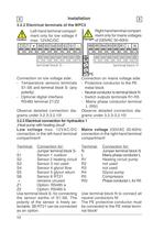
3 Installation 3 3.2.2 Electrical terminais of the WPC5 A Left-hand terminal compart-/!\ ment only for low voltage if Right-hand terminal compartiment only for mains voltages Caution max. 12VAC/DC Danger of 230VAC 50-60Hz Z2 □ Z1 □ + □ S6 □ S5 □ S4 □ S3 □ S2 □ S1 □ n □ □ □ □ □ □ S R5I □ R5 □ R4 □ R3 □ R2 □ R1 □ L □ N n 0 0 0 □ □ □ □ □ □ m terminal block S PE termina block N Connection on low voltage side: - Temperature sensors terminals S1-S6 and terminal block S- (any polarity) - Optional digital interface RS485 terminal Z1/Z2 Observe detailed connection dia-grams under 3.2.3-3.2.10! Connection...
Open the catalog to page 10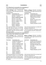
_3_ Installation _3_ 3.2.4 Electrical connection for hydraulics 2 Heat pump with heating circuit buffer" Lowvoltagemax. 12VAC/DC connection in the left-hand terminal compartment! Terminal: Connection for: Jumper terminal block S- 51 Sensor 1 outdoor 52 Sensor 2 heating circuit buffer 53 Sensor 3 not used 54 Sensor 4 glycol flow 55 Sensor 5 glycol return 56 Sensor 6 RT21 + remains unused Z1 Option: RS485 a Z2 Option: RS485 b Use terminal block S- for connecĭting the sensor earths of S1-S6. The polarity of the sensor is freely selectable. S6 RT21 can be connec-ted as an option. Mains voltage 230VAC...
Open the catalog to page 11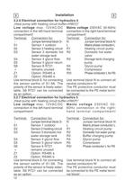
~3~| Installation 3.2.6 Electrical connection for hydraulics 4 Heat pump with heating circuit buffer+HW(V)" 3_ Low voltage max. 12VAC/DC connection in the left-hand terminal compartment! Terminal: Connection for: Jumper terminal block S- 51 Sensor 1 outdoor 52 Sensor 2 heating circuit 53 Sensor 3 domestic hot water storage tank 54 Sensor 4 glycol flow 55 Sensor 5 glycol return 56 Sensor 6 RT21 + remains unused Z1 Option: RS485 a Z2 Option: RS485 b Use terminal block S- for connecting the sensor earths of S1-S6. The polarity of the sensor is freely selec-table. S6 RT21 can be connected as an option....
Open the catalog to page 12All SOREL GmbH Mikroelektronik catalogs and technical brochures
 Catalogue 2021
72 Pages
 BA CALEONboxClima
34 Pages
 BA CALEONbox
32 Pages
 SOREL CATALOGUE 2013
56 Pages
 FWC
FWC32 Pages
 hcc
hcc4 Pages
 TDC
TDC8 Pages
