- Catalogs
- SOREL GmbH Mikroelektronik
- BA CALEONbox
BA CALEONbox
1 /32Pages

BA CALEONbox
1 /32Pages
Catalog excerpts
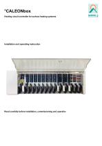
°CALEONbox Heating circuit controller for surface heating systems Installation and operating instruction Read carefully before installation, commissioning and operation
Open the catalog to page 1
CONTENT Safety Instructions EU-Conformity General instructions Explanation of Symbols Changes to the Unit Warranty and Liability Disposal and Pollutants Description °CALEONbox Description Specifications Scope of Supply Installation Wall Installation Electrical Connection Electrical Terminals LED status Connection Examples Room Controller Connection example apartment building Connection Examples 1-Wire Sensors 1-Wire ID overview Setup Wizard Room Overview Operating Mode Menu Set Operation Hours Set Operation Hours Expert Menu Settings Devices Rooms Temperature/Humidity Functions °Cbox Zones Example...
Open the catalog to page 2
Safety Instructions EU-Conformity By affixing the CE mark to the unit the manufacturer declares that the°CALEONbox conforms to the following relevant safety regulations: l l l l EU low voltage directive 2014/35/EU EU electromagnetic compatibility directive 2014/30/EU EU RoHS Directive 2011/65/EU EU WEEE Directive 2012/19/EU (Reg.nr. DE 23479719) conforms. Conformity has been verified and the corresponding documentation and the EU declaration of conformity are kept on file by the manufacturer. General instructions Please read carefully! These installation and operating instructions contain basic...
Open the catalog to page 3
Changes, additions to or conversion of the unit are not permitted without written permission from the manufacturer. It is likewise forbidden to install additional components that have not been tested together with the unit. If it becomes clear that safe operation of the unit is no longer possible, for example because of damage to the housing, turn the Unit off immediately. Any parts of the unit or accessories that are not in perfect condition must be exchanged immediately. Use only original spare parts and accessories from the manufacturer. Markings made on the unit at the factory must not be...
Open the catalog to page 4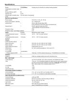
Specifications Model °CALEONbox Heating circuit controller for surface heating systems Temperature controller class 8 (ErP) Energy efficiency (ErP) 5% Standby loss 0,5 W Request type invertible heat "On /off" and/or "modulating" pump Electrical specifications: Power supply Power consumption / standby Internal fuse 1 1 Internal fuse 2 Protection Class Protection class / overvoltage category Inputs 1-Wire temperature sensor parasitic 1-Wire temperature sensor powered Outputs Switching relay outputs Relay heat pump Relay actuator Relay additional function PWM output 0-10V output 0-10V/PWM + Voltage...
Open the catalog to page 5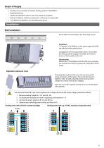
Heating circuit controller for surface heating systems°CALEONbox Replacement fuse additional separation wall for use of non-230V AC actuators DIN rail H=35mm L=280mm 2 screws 3,5 x 35 mm and 2 dowels S6 °CALEONbox Installation and operating instructions Installation Wall Installation Fix the DIN rail horizontally to the wall using screws. Installation 1. Place the °CALEONbox on the upper edge of the DIN rail with the locking catch on top. 2 Engage the device by pressing it down. Ensure that the locking catches engage completely and that the device is firmly seated on the rail. Disassembly Remove...
Open the catalog to page 6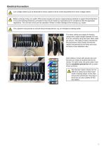
Electrical Connection Low-voltage cables such as temperature sensor cables must be routed separately from mains voltage cables. Before working on the unit, switch off the power supply and secure it against being switched on again! Check that there is no power flowing! Electrical connections may only be made by a specialist and in compliance with the applicable regulations. The unit may not be put into operation if there is visible damage to the housing, e.g. cracks. The customer must provide an all-pole disconnecting device, e.g. an emergency heating switch. The strain reliefs are suitable for...
Open the catalog to page 7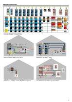
Electrical Terminals Example Wiring of Terminal Blocks Mains connection heating circuit pump Actuators for the heating zones Potential-free switching contacts for additional functions °CALEON Room Controller in private CAN bus
Open the catalog to page 8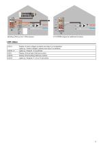
0-10V/PWM outputs for additional functions Flashes, if mains voltage is present and relay A is not switched Lights up, if mains voltage is present and relay A is switched. Lights up, if relay B - K is switched. Flashes, if the private CAN bus is active. Flashes, if the building CAN bus is active. Lights up, if outputs V1, V2 or V3 are active.
Open the catalog to page 9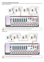
Connection Examples Room Controller Example 1: Tree Structure A 120 Ohm terminating resistor must be set on the first and last device in the CAN network. A 120 Ohm terminating resistor must be set on the first and last device in the CAN network.
Open the catalog to page 10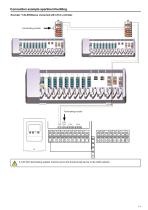
Connection example apartment building Example: °CALEONboxes connected with LHCC controller A 120 Ohm terminating resistor must be set on the first and last device in the CAN network.
Open the catalog to page 11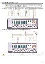
Connection Examples 1-Wire Sensors When connecting the 1-Wire sensors, please record the 16-digit 1-Wire ID and the location of the sensor for later commissioning of the system! The 1-Wire ID can be found in the device housing and in the device menu under: Devices -> °CALEONbox -> Resources -> 1-Wire sensor. Example 1: Line. The installation leads from one sensor to the next. A twisted pair cable must be used for the connecting cable. Example 2: Tree Structure. A twisted pair cable must be used for the connecting cable. Only the GND and 1-wire data terminals are used in parasitic operation (two...
Open the catalog to page 12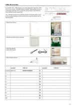
1-Wire ID overview For systems with 1-Wire sensors, you must assign the respective 1-Wire ID to a room on the °CALEON Room Controller. Writing down the IDs in combination with the room in which the sensor hangs in the following list simplifies the later assignment. The 1-Wire ID can be found inside the sensor on the type plate (1) and on the supplied sticker (2). We recommend to insert the sticker into the following table. 1-Wire Room Sensor flush-mounted 1-Wire Pipe Sensor 1-Wire Floor Sensor Location Example Bathroom
Open the catalog to page 13All SOREL GmbH Mikroelektronik catalogs and technical brochures
 Catalogue 2021
72 Pages
 BA CALEONboxClima
34 Pages
 SOREL CATALOGUE 2013
56 Pages
 wpc
wpc40 Pages
 FWC
FWC32 Pages
 hcc
hcc4 Pages
 TDC
TDC8 Pages
