MAIN UNIT P4018
1 /2Pages
MAIN UNIT P4018
1 /2Pages
Catalog excerpts
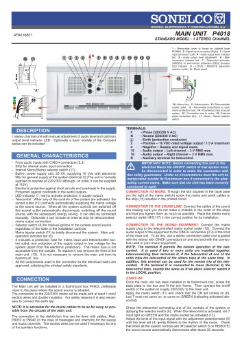
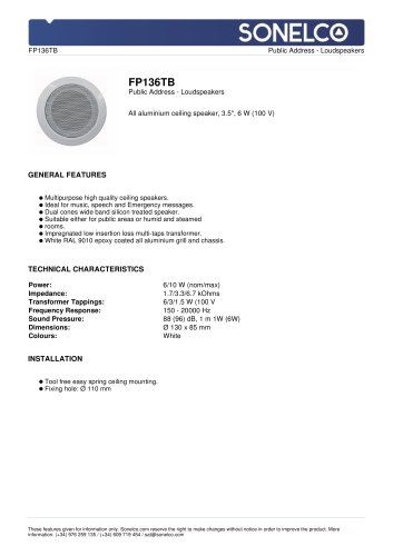
MAIN UNIT P4018 STANDARD MODEL - 1 STEREO CHANNEL 1 - Removable cover to house an optional tuner PC3664. 2 - Signal input connector (Right). 3 - Signal input connector (Left) 4 - Audio output level indicator led. 5 - Audio output level adjustment. 6 - Main connection indicator led. 7 - Telecontrol activation (GREEN) or short-circuit protection (RED) bi-colour LED indicator 8 - LOCAL / REMOTE telecontrol selector switch. 9 - Blank panel. 10 - Mains fuse. 11 - Mains switch. 12 -Telecontrolled socket outlet. 13 - Removable cover/frame to reach mains protection fuse. 14 - Connection strip to sound system. 15 - Connection strip to mains. 16 - External audio connection strip. 17 - Mono / Stereo selector switch. DESCRIPTION 1 stereo channel unit with manual adjustment of audio level and optimum output level indicator LED. Optionally a tuner module of the Compact series can be included. GENERAL CHARACTERISTICS - Front audio inputs with CINCH connectors (2,3) Strip for internal audio input connection Internal Mono/Stereo selector switch (17). Built-in power supply unit, 25 VA, supplying 16 Vdc with electronic filter for general supply of the system (terminal 2) (The unit is normally supplied to operate at 220/230V although, on order, it can be supplied at 110V). Electronic protection against short circuits and overloads in the supply. Protection against overloads in the audio outputs. LED indicator (7, red) to activate protection in supply output). Telecontrol. When any of the controls of the system are activated, the socket outlet (12) connects automatically supplying the mains voltage to the sound source. When all the system controls are switched off this socket outlet automatically disconnects, switching off the sound source, with the subsequent energy saving. It can also be connected manually. Optionally it can include an internal strip for telecontrolled mains output connection. Selector switch (8) for manual ignition of the outside sound source regardless of the state of the installation controls. Mains bipolar switch (11) to totally disconnect the system. Main unit operation indicator led (6). It includes a protection fuse for mains input and telecontrolled socket outlet, and protection of the supply output in low voltage for the system (apart from the electronic protection). The mains fuse is not accessible from the outside. To replace it, just remove the front of the main unit (13). It is not necessary to remove the main unit from its flushmount box. All the components used in the connection to the electrical mains are approved, satisfying the strictest safety standards. CONNECTION The Main unit will be installed in a flushmount box P4902, preferably close to the place where the sound source is situated. The connection to the 220/230V mains will be made with at least 1-mm2 section wires and double insulation. For safety reasons it is also necessary to connect the earth tap. NOTE: It is advisable for the mains cables to be as far away as possible from the circuits of the main unit. The connection to the distribution line can be done with cables, Mod. P9910 or P9940 (in the case of messages and intercom) for the supply and music channels. The excess wires can be used if necessary for any of the auxiliary functions. TERMINALS: F - Phase (220/230 V AC) N - Neutral (220/230 V AC) - Earth (protection conductor) 2 - Positive – 16 VDC rated voltage output / 1.5 A maximum 4 - Negative – Supply and signal mass. 15 - Audio output – Left channel – 3 V RMS max. 16 - Audio output – Right channel – 3 V RMS max. R - Auxiliary terminal for telecontrol. IMPORTANT NOTE: Before connecting this unit to the electrical Mains the ON/OFF switch of that system must be disconnected in order to make the connection with due safety guarantees. Under no circumstances must the unit be manipulated outside its flushmount box if connected to the alternating current mains. Make sure that the Unit has been correctly connected to earth. CONNECTION TO MAINS: Through the slot situated in the base plate (on the right of the mains switch) screw the mains and earth cables to the strip (15) situated in the printed circuit. CONNECTION TO THE SOUND LINE: Connect the cables of the sound line making sure you do not make a mistake in the order of the strips and that you tighten them as much as possible. Place the stereo mono selector switch M/S (17) in the correct position for its installation. CONNECTION TO THE SOUND EQUIPMENT: Connect the mains supply plug to the telecontrolled mains socket outlet (12). Connect the audio output of the equipment to the CINCH connectors (2,3) of the front of the main unit. To do this, use a stereo connection cable (not supplied with the mains) with CINCH connectors on one end and with the connectors used in your music equipment. NOTE: The terminal R permits the remote operation of the telecontrol. It is used if two or more units are installed together. Interconnecting their terminals R, if the telecontrol of one of the units trips the telecontrol of the others trips at the same time. In addition, this terminal can be used for the remote trip of the telecontrol. If the terminal R is connected to mass (terminal 4) the telecontrol trips, exactly the same as if we place selector switch 8 in the LOCAL position. START-UP: Once the main unit has been installed in its flushmount box, screw the base plate to the box and fit the trim frame. Then connect the on/off switch of the system to supply 220/230V to the main unit. Apply the mains switch (11) and check that the ON led comes on (6). Led 7 must not come on, or come on GREEN (indicating activated telecontrol). Check the telecontrol connecting one of the controls of the system or applying the selector switch (8). When the telecontrol is activated, led 7 must light up GREEN and the mains socket be activated (12). Adjust the level of the input signal with the adjustment potentiometer (5) until the level led (4) gently flickers to the rhythm of the music. Check that when all the system controls are off (selector switch 8 on REMOTE) the sound source automatically disconnects after about 30
Open the catalog to page 1All Sonelco catalogs and technical brochures


- Indoor home theater
- Home speaker
- Black home theater
- Rectangular home theater
- White stereo speaker
- Multimedia speaker
- Metal speaker
- Amplifier
- Round speaker
- Wooden audio system
- Audio amplifier
- Aluminum loudspeaker
- Exterior speaker
- Built-in audio system
- Plastic speaker
- Built-in speaker
- Interface module
- Wooden speaker
- Floor-standing audio system
- Floor-standing speaker