KXD_MANUAL
1 /188Pages

KXD_MANUAL
1 /188Pages
Catalog excerpts
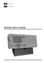
Boiler controller
Open the catalog to page 1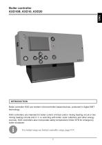
INTRODUCTION Boiler controller KXD are modern microcontroller based devices, produced in digital SMT technology. KXD controllers are intended for boiler control of direct and/or mixing heating circuit or two mixing heating circuits and d. h. w. warming with boiler, solar collectors and other energy sources. KXD controllers also incorporate safety temperature limiter STB for emergency boiler shutdown. For initial setup see Initial controller setup, page 9 9!
Open the catalog to page 5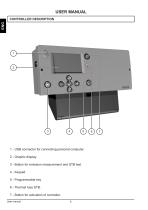
CONTROLLER DESCRIPTION 1 - USB connector for connecting personal computer. 2 - Graphic display. 3 - Button for emission measurement and STB test. 4 - Keypad 5 - Programmable key 6 - Thermal fuse STB. 7 - Button for activation of controller. User manual
Open the catalog to page 8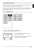
INITIAL CONTROLLER SETUP KXD heating controllers are equipped with an innovative solution “Easy start” which enables the setup of controller in just three or four easy steps. When the controller is connected to the power supply for the first time, the display first shows the program version and company logo and then the first step of the procedure for controller settings is started. STEP 1 - LANGUAGE SETUP Use buttons — and + to select the requested language. Confirm the selected language by pressing >/. The controller requires a confirmation of language selection with the y button. In case you...
Open the catalog to page 9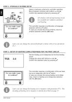
STEP 2 - HYDRAULIC SCHEME SETUP Select a hydraulic scheme for controller operation. Move between schemes with buttons — and Confirm the selected scheme by pressing >/. All schemes with mixing heating circuit are available for radiators and floor/ wall heating. Do you reallv want to continue? The controller requires a confirmation of language selection with the V button. In case you choose the wrong scheme, return to scheme selection with the ^ button. Later you can change the selected hydraulic scheme with service parameter S1.1. STEP 3 - SETUP OF HEATING CURVE STEEPNESS FOR THE FIRST CIRCUIT...
Open the catalog to page 10
STEP 4 - SETUP OF THE HEATING CURVE STEEPNESS FOR THE SECOND CIRCUIT1 Do you reallY want to continue? Set the heating curve steepness for the second heating circuit. Change the value with buttons — and +. Confirm the selected value by pressing >/. The controller requires a confirmation of the set heating curve steepness with the >/ button. In case you choose the wrong heating curve steepness, return to heating curve steepness selection with the ^ button. Later you can change the heating curve steepness with parameter P3.1. The meaning of heating curve steepness is detaily described on page 37....
Open the catalog to page 11
KEYPAD AND OTHER KEYS SAFETY TEMPERATURE LIMITER STB Safety temperature limiter is used as a thermal protection of heat source. It disconnects heat source power supply if temperature of heat source exceeds 110 °C. Activated safety temperature limiter is indicated with red illuminated STB text. A If a safety temperature limiter STB activates in normal operation mode a qualified service person needs to check the heating system for proper operation before continuing with system operation.
Open the catalog to page 12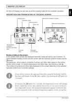
On the LCD display we can look up all the important data for the controller operation. DESCRIPTION AND PRESENTATION OF THE BASIC SCREEN: State of the controller‘s outputs. Heating circuit. Operation mode. Active functions. Measured temperatures. Room unit. Temperatures, protection functions and other data. Review of data on the screen: In the middle of the screen are displayed operation mode and active user functions. To switch between heating circuits and the screen with the hydraulic scheme review use the button. Temperatures, active outputs, protection functions and other data appear in the...
Open the catalog to page 13
DESCRIPTION OF SYMBOLS PRESENTED ON THE DISPLAY SYMBOLS FOR HEATING CIRCUITS * The number indicates the first or the second time program.
Open the catalog to page 14
* The number indicates the first or the second heating circuit.
Open the catalog to page 15
SYMBOLS FOR MESSAGES AND WARNINGS HELP, MESSAGES AND WARNINGS SCREEN By pressing the ? button, the help, messages and warnings screen is retrieved. A new window opens with the following icons: Short instructions Short instructions on the use of controller. Controller version Review of the controller type and program version. Messages List of exceeded maximum temperatures and list of activated protection functions. By pressing the buttons — and + navigate through the list of messages. Exit the list by pressing the ^ button. Warnings List of sensors and other component malfunctions. By pressing...
Open the catalog to page 19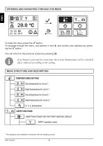
ENTERING AND NAVIGATING THROUGH THE MENU To enter the menu press the >/ button. To navigate through the menu, use buttons — and +, and confirm your selection by pressing the >/ button. You can return to the previous screen by pressing ^. If no button is pressed for some time, the screen illumination will be switched off or reduced according to the setting. * The setting is only available in schemes with two heating circuits.
Open the catalog to page 20
ECO operation mode. Holiday operation mode. Function switch-off. 3DD2 USER FUNCTIONS FOR THE SECOND HEATING CIRCUIT * PARTY operation mode. ECO operation mode. Holiday operation mode. X Function switch-off. €C0 USER FUNCTIONS FOR D. H. W. One-time switch-on of d. h. w. warming. Function switch-off. USER FUNCTIONS FOR ENERGY SOURCES ** One-time switch-on of liquid fuel boiler. Switch-off (block) of liquid fuel boiler. Start-up of solid fuel boiler. X Function switch-off. (!) OPERATION MODE SELECTION OPERATION MODE FOR THE FIRST HEATING CIRCUIT Operation mode according to selected time program....
Open the catalog to page 21
OPERATION MODE FOR THE SECOND HEATING CIRCUIT* (!) Operation mode according to selected time program. Requested room temperature is set on the controller or room unit, if connected. Operation mode according to day temperature. Requested room temperature is set on the controller. Operation mode according to night temperature. Requested room temperature is set on the controller. Switch-off. OPERATION MODE FOR D. H. W. WARMING D. h. w. warming according to selected time program. Permanent switch-on of d. h. w. warming. Switch-off. ON (!) SELECTION OF OPERATION MODE HEATING OR COOLING MANUAL OPERATION...
Open the catalog to page 22All Seltron catalogs and technical brochures
 Seltron Controllers Catalogue 2021
176 Pages
 Catalogue 2020
150 Pages
 Catalogue SELTRON 2019
150 Pages
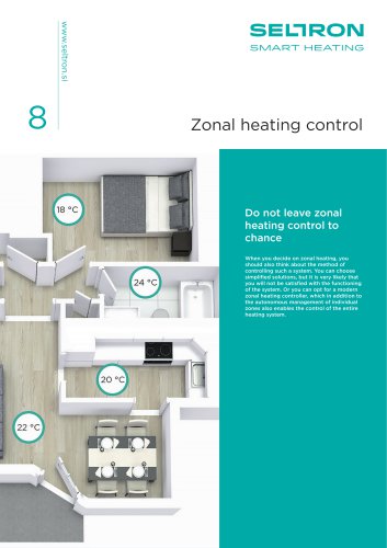 Zonal heating control
4 Pages
 KXD_DATA SHEET
12 Pages
 SeltronHome-2017-marec-ENG
36 Pages
 KATALOG-TT-ENG-2017
108 Pages
 Product catalog 2015
114 Pages
 2013 Product catalogue
92 Pages
- Industrial thermostat
- White thermostat
- Programmable thermostat
- Heating thermostat
- Digital thermostat
- Wall-mounted thermostat
- Thermostat with digital display
- Room thermostat
- Interface module
- Indoor control module
- Wireless thermostat
- Home control module
- Multifunction sensor
- Gateway interface module
- Home automation system control module
- Single function sensor
- DIN rail control module
- Underfloor heating thermostat