- Company
- Products
- Catalogs
- News & Trends
- Exhibitions
VARS
1 /26Pages
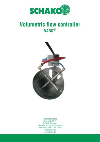
VARS
1 /26Pages
Catalog excerpts

08/14 - 2 Construction subject to change. Version: 09.05.2019 No return possible!
Open the catalog to page 2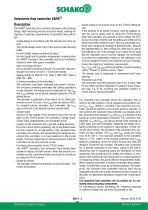
Volumetric flow controller VARS® Description ® The VARS volumetric flow controller impresses with its simple design, high measuring precision and short length, meeting the majority of customary requirements of volumetric flow controllers. - simple design in accordance with the nominal size of the air duct. This simple design saves a lot of time and provides planning safety. - its short length reduces problems of space. Its short length and its position-independent mounting allow the VARS® volumetric flow controller also to be mounted in situations where little space is available. - high controlling...
Open the catalog to page 3
Field of application - for supply and return air systems - for constant or variable volumetric flows - Positive control Vmin, Vmax, "OPEN" or “CLOSED” - Suitable for constant and variable volumetric flow or duct pressure control - differential pressure range from 20 to 1000 Pa - for duct velocities of 1 - 12 m/s - for ambient temperatures of 0 - 50°C When installing volumetric flow controllers, for example in roof central units, in extreme cases, condensation can build up in the measuring pipes of the volumetric flow controller as a result of the large temperature differences between the air...
Open the catalog to page 4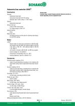
Volumetric flow controller VARS® Construction Please note! Housing Tension rings, counter flanges and duct silencers must be or- Galvanised sheet steel dered separately and are supplied loose! - Galvanized sheet steel with DD coating - Stainless steel 1.4301 (V2A) or 1.4571 (V4A) Damper - Galvanised sheet steel Damper leaf seal - made of PUR, silicone-free - for airtight design to DIN 1751 Damper bearing - Brass Measuring rods - Extruded aluminium profile (also for stainless steel design, but with DD coating) Model VARS® - Round model, for spiral duct connection to DIN EN 1506, with damper leaf...
Open the catalog to page 5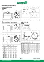
Models and dimensions Dimensions VARS® Metu flange (-MF1/-MF2) / counter flange (-GF) (pair, loose), on both sides, loose/ tension ring (-SR) (pair), on both sides, loose Flat-bed acoustic cladding (-FD1, insulation 3mm) Please note! Tension rings and counter flanges must be ordered separately and are supplied loose! Rubber lip seal (-GD1) Detail X Available sizes VARS® / ..-FD1 / ...-DS2 Construction subject to change.
Open the catalog to page 6
Duct silencer (-RS) Available sizes duct silencer (-RS) NW Insertion loss Duct silencer (-RS) Construction subject to change.
Open the catalog to page 7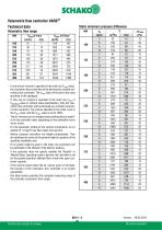
Technical dataVolumetric flow range Static minimum pressure difference NW - If only one air volume is specified in the order (as Vmax value), the volumetric flow controller will be delivered as variable volumetric flow controller. The Vmin value will be set to the value specified in the catalogue. - If only one air volume is specified in the order (as Vmin or Vkonstant value or without value specification), then the volumetric flow controller will be delivered as a constant volumetric flow controller. The volume specified in the order is set to the Vmin value, and the Vmax value is set to 100%....
Open the catalog to page 8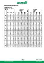
Flow generated noise Pressure loss 125 Pa and 250 Pa Construction subject to change.
Open the catalog to page 9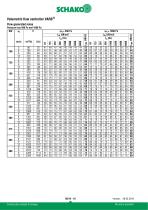
Volumetric flow controller VARS® Flow generated noise Pressure loss 500 Pa and 1000 Pa NW Version: 09.05.2019 No return possible! Construction subject to change.
Open the catalog to page 10
Radiated noise Pressure loss 125 Pa and 250 Pa Version: 09.05.2019 Construction subject to change. No return possible!
Open the catalog to page 11
Volumetric flow controller VARS® Radiated noise Pressure loss 500 Pa and 1000 Pa NW Construction subject to change.
Open the catalog to page 12
Volumetric flow controller VARS® 08/14 - 13 Construction subject to change. Flow generated noise with duct silencer L= 950 Version: 09.05.2019 No return possible!
Open the catalog to page 13
Volumetric flow controller VARSFlow generated noise with duct silencer L= 950 Pressure loss 500 Pa and 1000 Pa Construction subject to change.
Open the catalog to page 14
Construction subject to change.
Open the catalog to page 15
Volumetric flow controller VARS® 08/14 - 16 Construction subject to change. Flow generated noise with duct silencer L= 1450 Version: 09.05.2019 No return possible!
Open the catalog to page 16
Volumetric flow controller VARS® Technical data for Belimo components Measured value collection and control function The measured values are collected by two measuring rods favourable to the flow. The measuring openings are distributed over the measuring rods according to the median line method. The pressure differential formed on the measuring rods is determined by means of a dynamic or static measuring sensor. From these measuring results the middle value is formed, which gives a measured variable for the volume flow. The controller compares the actual value signal with the set point and sends...
Open the catalog to page 17
Volumetric flow controller VARS® CAV operation / positive contacts Circuit diagrams Compact controller Belimo make LMV-D3-MF - Attention: not MP-bus-capable VAV with analogue command signal VAV with lock (CLOSED) Mode 2-10V DC actual value signal "0...10V / 2...10V Switchover CLOSED / VAV operation actual value signal Note: Please ensure mutual lockingof the contacts! Cable designations Mode setting Signal Lock mode (CLOSED) In the 2 - 10 V mode, the following function can be carried out with a 0 - 10 V signal: **Attention: Controller/DDC must be able to pull the command signal to 0 V. Function...
Open the catalog to page 18
Volumetric flow controller VARSLED table of functions for LMV-D3-MF Application Adaptation Address power status green LED (power) is lit | | yellow LED (status) is lit Construction subject to change.
Open the catalog to page 19
Volumetric flow controller VARS® Setting the operating potentiometers / calculation formulae Actual value measurement via feedback signal U5 using a voltmeter or PC-Tool The required volumetric flow that is to flow at the 10 V DC command signal at terminal 3 (Y) or with positive control Vmax is set in % at the Vmax potentiometer of the controller, the ZTH-EU or PC-Tool. This value refers to the set Vnenn nominal volumetric flow. Set value for Vmin EW V Supply voltage: 24 V AC/DC (Terminals 1+2) Measurement output 2 - 10 V DC (Terminals 1+5) Measurement output 0 - 10 V DC (Terminals 1+5) The actual...
Open the catalog to page 20All SCHAKO KG catalogs and technical brochures
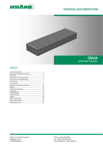 CNVA
CNVA32 Pages
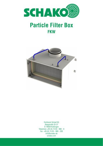 FKW (2025)
28 Pages
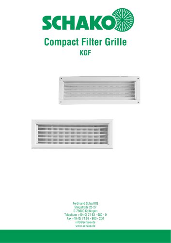 KGF Compact Filter Grille
9 Pages
 AUDIX
AUDIX2 Pages
 DISA
DISA4 Pages
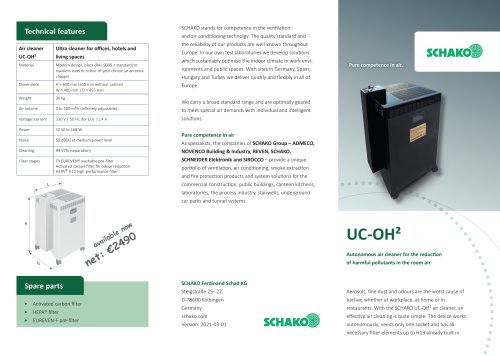 UC-OH²
2 Pages
 IGA
IGA2 Pages
 CDD
CDD2 Pages
 FBS
FBS18 Pages
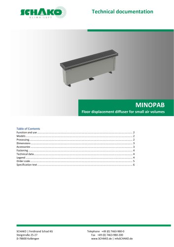 MINOPAB (2025)
6 Pages
 PIL
PIL23 Pages
 MWS / MWK
23 Pages
 ERK-SO
43 Pages
 DSCXL
DSCXL17 Pages
 DSCPL
DSCPL16 Pages
 BKSYS
BKSYS18 Pages
 MINODSA
6 Pages
 DKA
DKA6 Pages
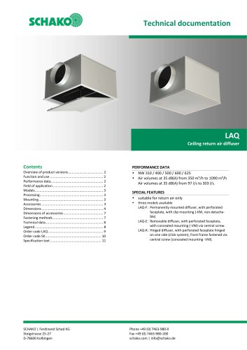 LAQ
LAQ11 Pages
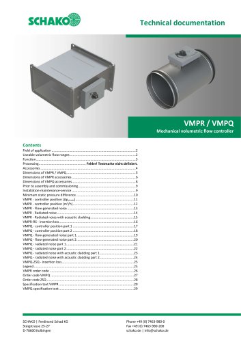 VMPR/VMPQ
29 Pages
 DSCU
DSCU18 Pages
 DSCP
DSCP15 Pages
 DQJP
DQJP9 Pages
 BKA-EN
79 Pages
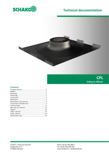 CPL
CPL15 Pages
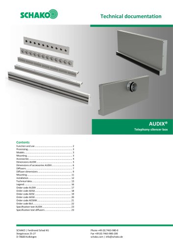 AUDIX®
25 Pages
 VREX
VREX26 Pages
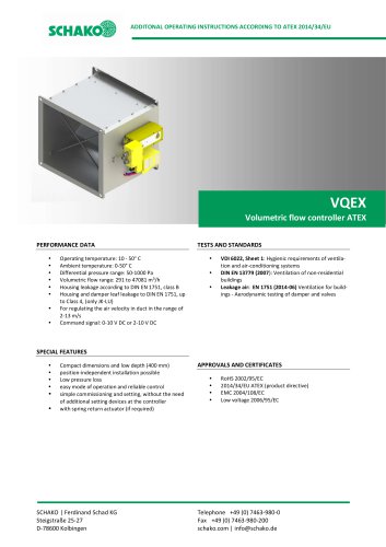 VQEX
VQEX17 Pages
 VPEX
VPEX18 Pages
 SVA-FS
11 Pages
 NRWG
NRWG22 Pages
 COMBIDSC
26 Pages
 DSC
DSC37 Pages
 DO
DO10 Pages
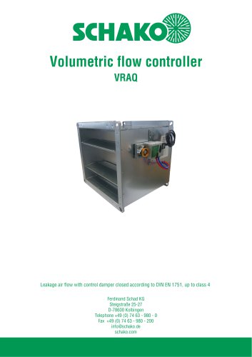 VRAQ
VRAQ46 Pages
 UEKU
UEKU6 Pages
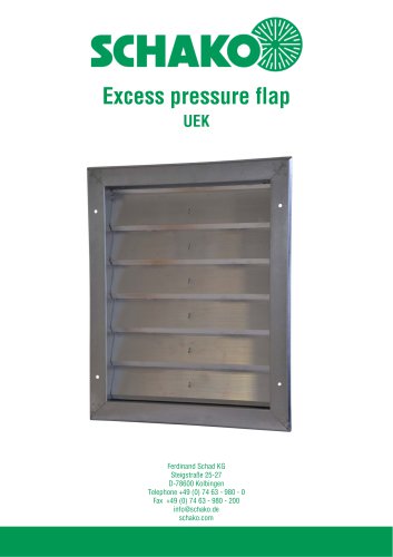 UEK
UEK6 Pages
 SS-K
SS-K6 Pages
 VOLKOM
6 Pages
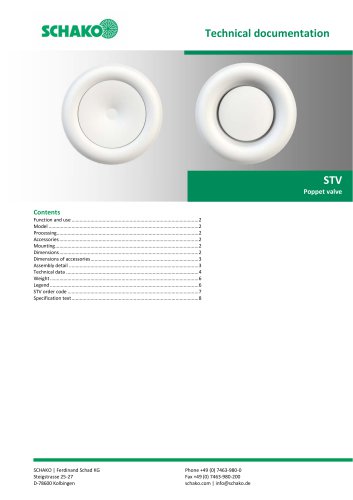 STV
STV8 Pages
 DQJ
DQJ38 Pages
 ALAS-F 125
6 Pages
 ALPETY
16 Pages
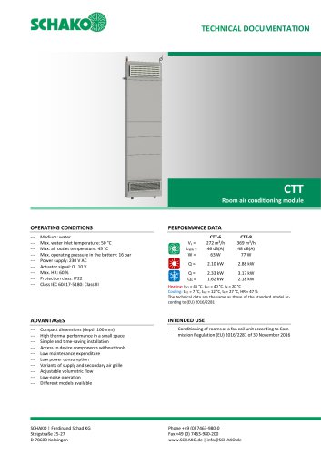 CTT
CTT23 Pages
 KWB
KWB19 Pages
 GREENKIT
20 Pages
 SVA-FF
15 Pages
 FKU
FKU31 Pages
 FKF
FKF29 Pages
 SGA
SGA5 Pages
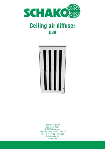 DBB
DBB27 Pages
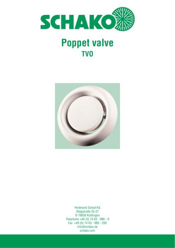 TVO
TVO8 Pages
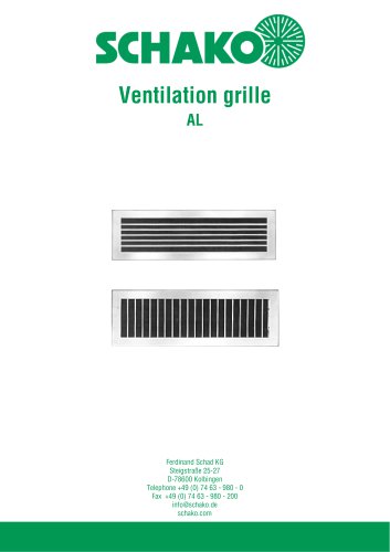 AL
AL23 Pages
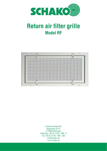
 RF Return air filter grille
7 Pages
 NBS
NBS34 Pages
 MKAR_MKAQ
13 Pages
 KF
KF4 Pages
 JK
JK16 Pages
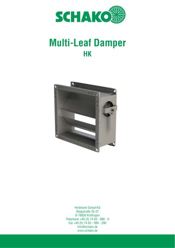 HK
HK16 Pages
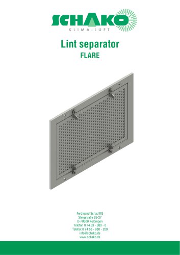
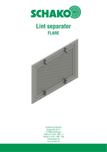 Lint Separator FLARE
13 Pages
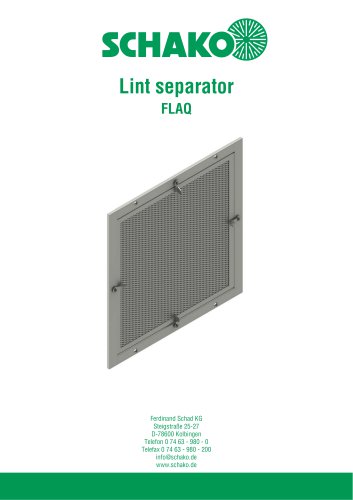 FLAQ
FLAQ11 Pages
 FG
FG14 Pages
 ERK-MB
38 Pages
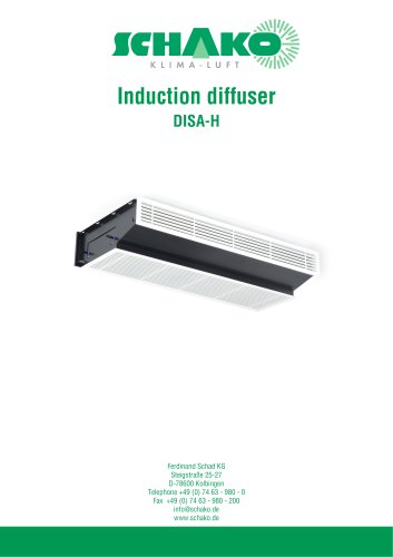
 DISA-H (2025)
34 Pages
 DISA-360
32 Pages
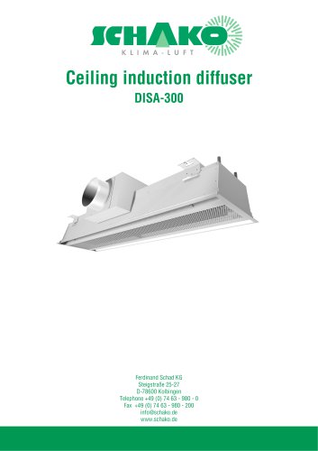 DISA-300
51 Pages
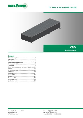 CNV
CNV29 Pages
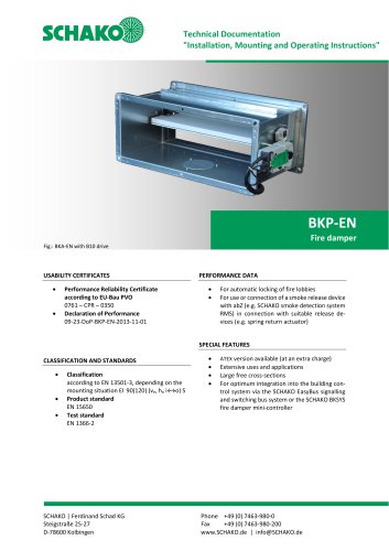
 BKP-EN Fire damper
40 Pages
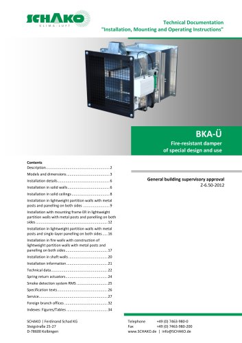 BKA-UE
35 Pages
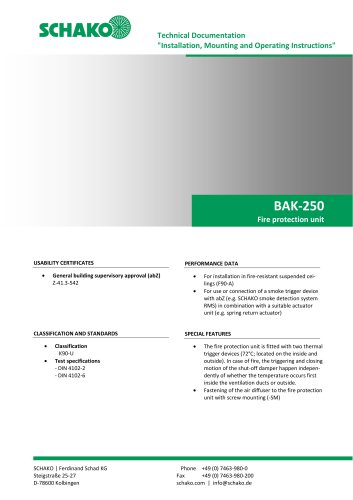 BAK-250 Fire protection unit
17 Pages
 BAK-240
16 Pages
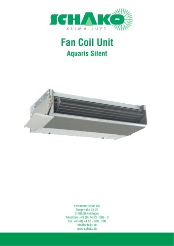
 Aquaris-Silent
38 Pages
 Aquaris_KWB
20 Pages
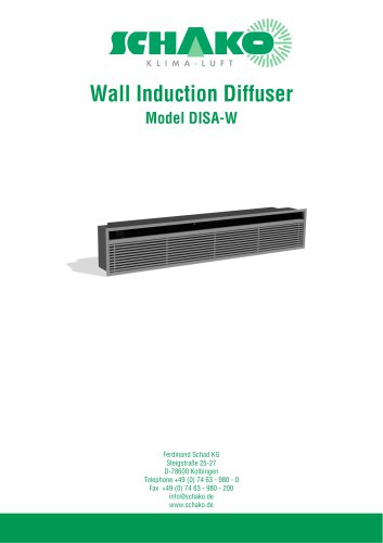 DISA-W
43 Pages
 CULTRA-Studioline
24 Pages
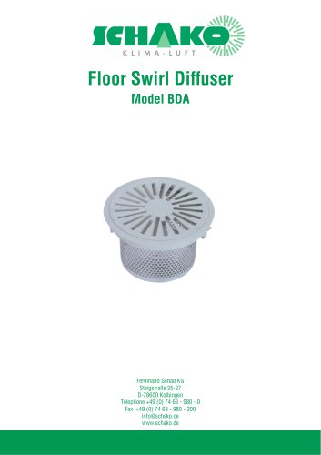 BDA
BDA11 Pages
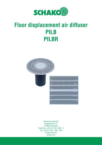 PILB/PILBR
33 Pages
 DAV
DAV19 Pages
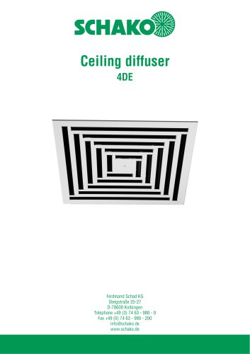 4DE
4DE18 Pages
 4DF
4DF13 Pages
 DQC
DQC16 Pages
 DQDL
DQDL16 Pages
 IDA
IDA21 Pages
 IKA
IKA23 Pages
 ZMD
ZMD17 Pages
 DQF
DQF15 Pages
 DQJF
DQJF12 Pages
 DQJA/DQJR
10 Pages
 DQJSL
DQJSL17 Pages
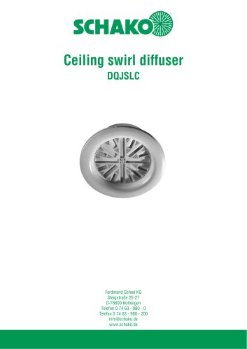 DQJSLC
17 Pages
 DHV
DHV18 Pages
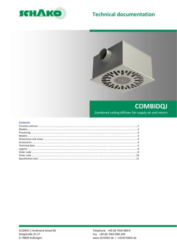 COMBIDQJ
11 Pages
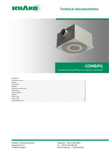 COMBIPIL
11 Pages
 DSA
DSA15 Pages
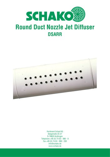 DSARR
DSARR7 Pages
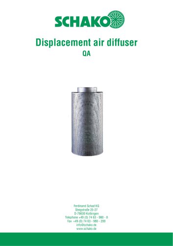 QA
QA30 Pages
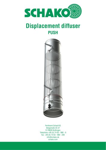 PUSH
PUSH23 Pages
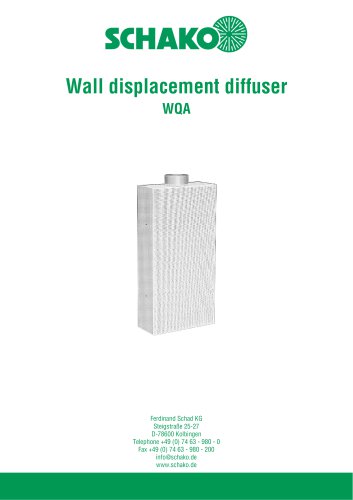 WQA
WQA12 Pages
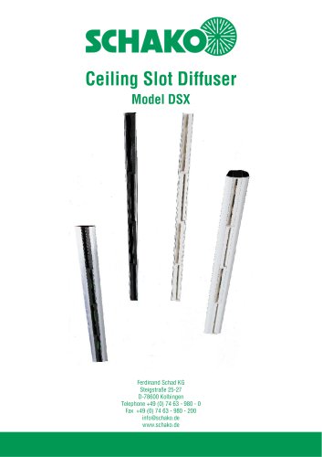 DSX
DSX25 Pages
 DSX-XXL
23 Pages
 AUDIX®-AW
20 Pages
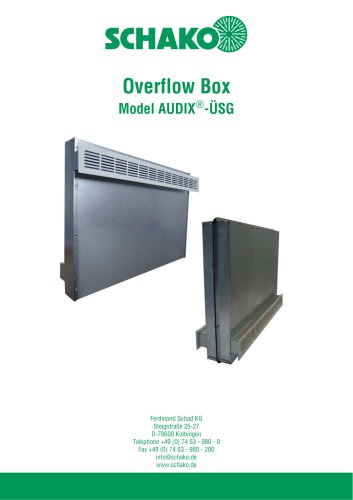 AUDIX®-ÜSG
13 Pages
 DSX-XXL-W
25 Pages
 SIA
SIA7 Pages
 SAR/SAQ/SARP
13 Pages
 WDA
WDA32 Pages
 BSG
BSG19 Pages
 KG
KG19 Pages
 IB-Q
IB-Q21 Pages
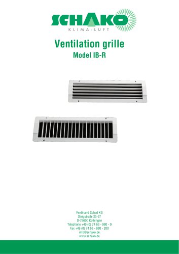 IB-R
IB-R15 Pages
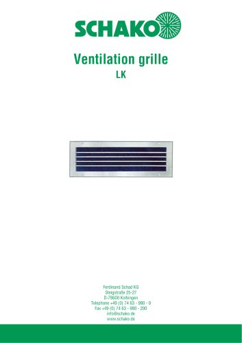 LK
LK12 Pages
 PA
PA32 Pages
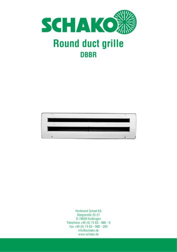 DBBR
DBBR6 Pages
 KGRR
KGRR17 Pages
 DBBRR
DBBRR11 Pages
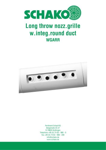 WGARR
WGARR7 Pages
 WGA
WGA29 Pages
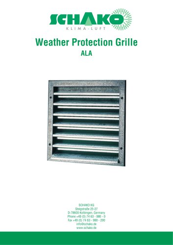 ALA
ALA4 Pages
 ALA-R
ALA-R4 Pages
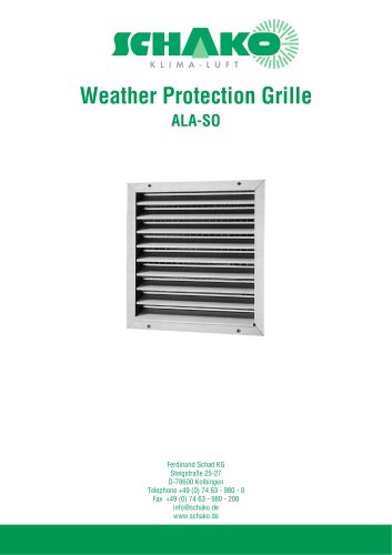 ALA-SO
4 Pages
 ALAS
ALAS10 Pages
 ALAS-P
5 Pages
 DKAPPs
6 Pages
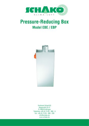 EBE/EBP
52 Pages
 DKG
DKG6 Pages
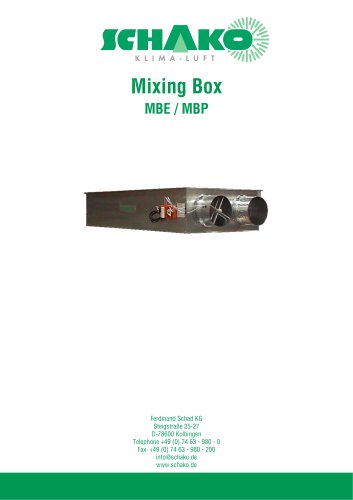 MBE/MBP
27 Pages
 PIANO
PIANO27 Pages
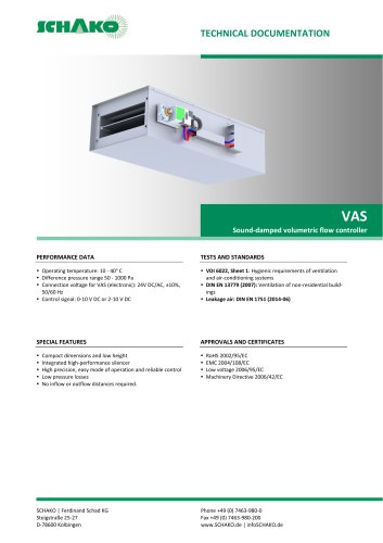 VAS
VAS26 Pages
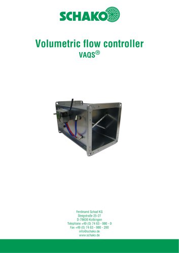 VAQS
VAQS19 Pages
 VRAPPs
20 Pages
 VRAR
VRAR52 Pages
 MAK
MAK15 Pages
 RS-F
RS-F7 Pages
 RS
RS15 Pages
 EasyBus
24 Pages
 DISA-Family
4 Pages
 RMS
RMS11 Pages
 TSR
TSR5 Pages
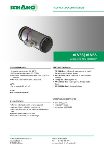 VLV
VLV31 Pages
 MBM
MBM10 Pages
 LL
LL7 Pages
 RR-Complete
41 Pages
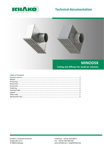 MINODSX
6 Pages
 SPB
SPB10 Pages
 DISA-H
34 Pages
 AQUARIS SILENT
38 Pages
 NBS
NBS24 Pages
 JK-LP/JK-LU
15 Pages
 HKP / HKU
16 Pages
 FKW
FKW16 Pages
 FLARE
FLARE13 Pages
 RF
RF7 Pages
 KGF
KGF9 Pages
 SVA-FF
8 Pages
 BKA-Ü
BKA-Ü35 Pages
 BSK-RPR
60 Pages
 BKP-EN
40 Pages
 BAK-240
6 Pages
 BAK-250
14 Pages


- Ventilation grill
- Industrial air conditioner
- Metal ventilation grill
- Rectangular ventilation grill
- Commercial detector
- Commercial air conditioning cabinet
- Industrial air diffuser
- Reversible air conditioner
- Aluminum ventilation grill
- Exterior ventilation grill
- Commercial ventilation grill
- Facade ventilation grill
- Ceiling-mounted air diffuser
- Industrial fan coil
- White ventilation grill
- Industrial convector
- Home ventilation grill
- Metal convector
- Contemporary convector
- Wall-mounted air conditioner