- Company
- Products
- Catalogs
- News & Trends
- Exhibitions
NRWG
1 /22Pages

NRWG
1 /22Pages
Catalog excerpts

Technical documentation SCHAKO | Ferdinand Schad KG Steigstrasse 25-27 D-78600 Kolbingen Declaration of Performance 09-53-DoP- JK-180MB-2014-11-01 09-53-DoP-JK-190-2014-11-01 EC Certificate of Conformity 1368-CPD-C-004/2013 Performance Reliability Certificate 1368-CPR-C-7050
Open the catalog to page 1
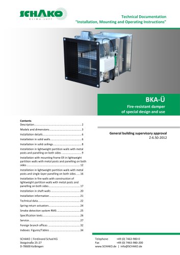
TECHNICAL DOCUMENTATION Function and use | Areas of application and requirements FUNCTION AND USE A natural smoke and heat exhaust ventilator (NRWG) is an important part of a smoke and heat exhaust ventilation system (RWA). In case of fire, it is used to remove hot gases from a building in order to protect people, material property and the environment. In case of fire, smoke and heat exhaust ventilation systems are supposed to ensure a smoke-free layer near the floor by removing a sufficient amount of the smoke gas from the smoke section. Moreover, in the initial fire, their function is to remove...
Open the catalog to page 2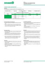
NRWG TECHNICAL DOCUMENTATION Capacity and classification | Summary The classifications for NRWG-180/ NRWG-190 are highlighted in colour. *) A is used as wild card for a certain value specified by the manufacturer Aerodynamically active opening area • Geometric opening area multiplied by the flow rate coefficient • Flow rate coefficient determined experimentally either directly or indirectly from the test results of NRWGs of different sizes or from scaled-down models Operational safety • Proof that the NRWG opens and closes during the number of specified cycles • The designations A, 50 and 1000...
Open the catalog to page 3
NRWG TECHNICAL DOCUMENTATION Processing |PROCESSING Frame • Profiled galvanised sheet steel 1,5 mm • Dimensionally stable • NRWG-180 - for flush-mounted installation with 180 mm frame depth and mounting plate • NRWG-190 - for surface-mounted installation with 190 mm frame depth • Bores for fastening the accessories Blades • Hollow-body aluminium blades • Flow-favouring and torsion-resistant • Block adjustment in opposite directions Seal • EPDM rubber profile Bearing • Sintered bearing Gear wheels • plastic PA6 • Arranged on one side • The flow-favouring aluminium blades are jointly adjusted in...
Open the catalog to page 4
MODEL NRWG-180/ NRWG-190 NRWG TECHNICAL DOCUMENTATION MODEL NRWG-180/ NRWG-190 | Size chart B and H components can be freely selected 1 = Frame (B part) 2 = Frame (H part) 3 = Actuator side (gear wheel cover) 4 = Actuator 5 = Blade Front view Drive side Gear wheels Blades Construction subject to change No return possible
Open the catalog to page 5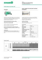
NRWG TECHNICAL DOCUMENTATION Drives NRWG-180/ NRWG-190 | DIRECT-CURRENT ACTUATOR (ONLY AVAILABLE ON REQUEST) Spring return actuator with emergency control function (currentless open) for adjusting air dampers. For use in openings for smoke removal and in daily ventilation operation. Suitable for interior assembly only. Electrical, with spring return (currentless OPEN) 20 Nm, 230 V AC, 2/3-point (-E024) 20 Nm, 24 V AC, 2/3-point (-E025) 20 Nm, 24 V AC/DC, 0-10 V DC with RJ45 plug (-E072) 20 Nm, 24 V AC/DC, 0-10 V DC (-E073) Electrical, with integrated limit switches (accessories) Actuator with...
Open the catalog to page 6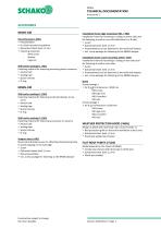
NRWG TECHNICAL DOCUMENTATION Accessories |ACCESSORIES NRWG-180 Mounting plate (-MB1) • Preassembled • For flush-mounted installation • Galvanised sheet steel 1,5 mm • Fastening materials - Allen screw - Washer - Cage nut Wall anchor package 1 (-M1) Fastening material for fastening mounting plate to masonry • Anchor bolt • Sealing tape • Spacer sleeves • O-ring NRWG-190 Wall anchor package 2 (-M2) Fastening material for fastening multi-leaf damper to masonry • Anchor bolt • Sealing tape • Spacer sleeves • O-ring Wall anchor package 3 (-M3) Fastening material for fastening accessories to masonry...
Open the catalog to page 7
NRWG TECHNICAL DOCUMENTATION Cross-sections and opening surface areas | GEOMETRIC OPENING SURFACE AREA (AV) AERODYNAMICALLY ACTIVE OPENING SURFACE AREA WITH WEATHER PROTECTION HOOD When using the NRWG multi-leaf damper with weather protection hood, the value of the aerodynamically active opening surface area of the weather protection hood must be taken into account. Construction subject to change No return possible
Open the catalog to page 8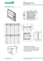
NRWG TECHNICAL DOCUMENTATION Dimensions NRWG-180 | Cable bushing Clear opening Cable bushing in the mounting plate In order to be able to feed a cable through the mounting plate area, a stepped spigot is mounted in factory. If necessary, this stepped spigot can be cut during the assembly to feed a cable through and can be used for cables with a diameter between 13 and 26,5 mm. The cable bushing has the degree of protection IP55. Construction subject to change No return possible
Open the catalog to page 9
NRWG TECHNICAL DOCUMENTATION Dimensions NRWG-190 | Clear opening Clear opening Construction subject to change No return possible
Open the catalog to page 10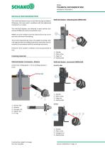
TECHNICAL DOCUMENTATION INSTALLATION INFORMATION The multi-leaf dampers must not be tilted during installation. Otherwise, this may result in problems with the adjustment mechanism or in leaks. Multi-leaf damper – Mounting plate (NRWG-180) The multi-leaf dampers are delivered in open position (currentless OPEN) and must be mounted as such. 4 NRWGs must be installed such that external forces do not impair their permanent functioning. They must be fastened by means of suitable mounting materials approved by the building supervisory authorities (see Accessories) in accordance with the mounting instructions....
Open the catalog to page 11
TECHNICAL DOCUMENTATION Fastening points Fastening points If required, the connecting cable of the actuator must be run through the opening provided in the mounting plate and fastened using the cable traction relief premounted on the connecting cable. Detail Construction subject to change No return possible
Open the catalog to page 12
TECHNICAL DOCUMENTATION INSTALLATION ACCESSORIES NRWG-190 Support sheet (-AB1) Fastening points Construction subject to change No return possible
Open the catalog to page 13
TECHNICAL DOCUMENTATION Installation frame edge mounting (-ER1 / -ER2) ER1 fastened to the wall via the bracket on the H part of the multi-leaf damper (opposite side of the actuator) ER2 fastened to the wall via the bracket on one of the two B parts of the multi-leaf damper Fastening points Construction subject to change No return possible
Open the catalog to page 14All SCHAKO KG catalogs and technical brochures
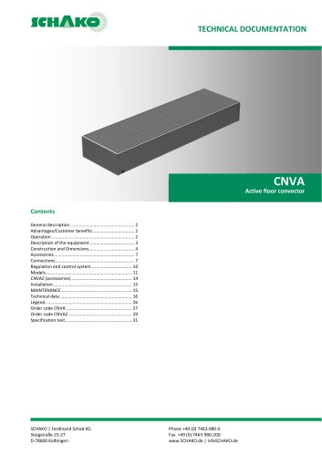 CNVA
CNVA32 Pages
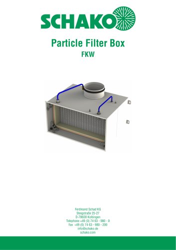 FKW (2025)
28 Pages
 KGF Compact Filter Grille
9 Pages
 AUDIX
AUDIX2 Pages
 DISA
DISA4 Pages
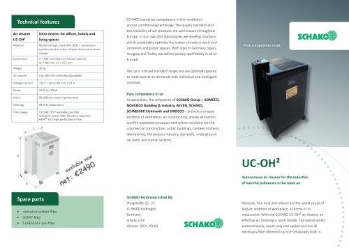 UC-OH²
2 Pages
 IGA
IGA2 Pages
 CDD
CDD2 Pages
 FBS
FBS18 Pages
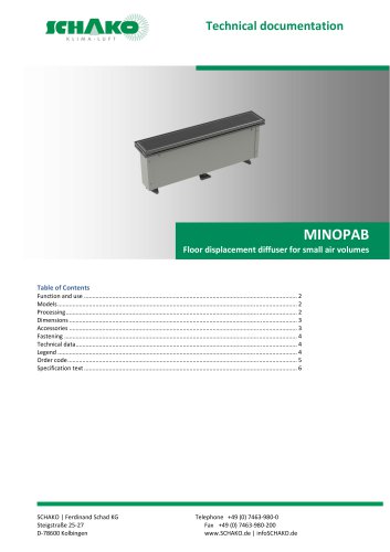 MINOPAB (2025)
6 Pages
 PIL
PIL23 Pages
 MWS / MWK
23 Pages
 ERK-SO
43 Pages
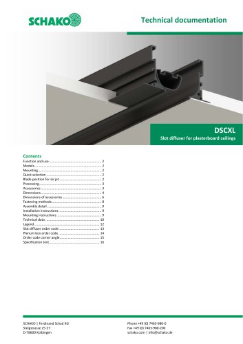 DSCXL
DSCXL17 Pages
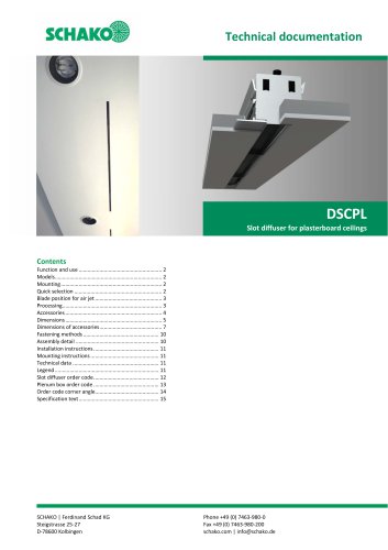 DSCPL
DSCPL16 Pages
 BKSYS
BKSYS18 Pages
 MINODSA
6 Pages
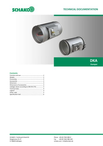 DKA
DKA6 Pages
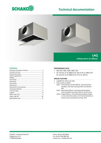 LAQ
LAQ11 Pages
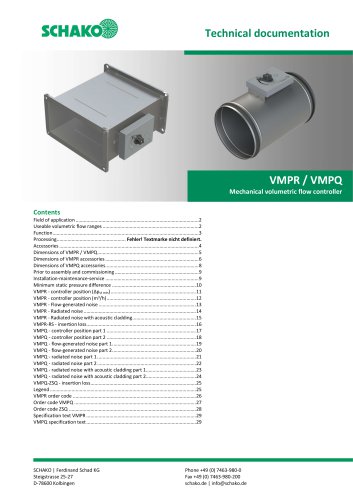 VMPR/VMPQ
29 Pages
 DSCU
DSCU18 Pages
 DSCP
DSCP15 Pages
 DQJP
DQJP9 Pages
 BKA-EN
79 Pages
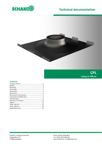 CPL
CPL15 Pages
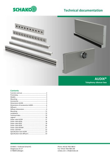 AUDIX®
25 Pages
 VREX
VREX26 Pages
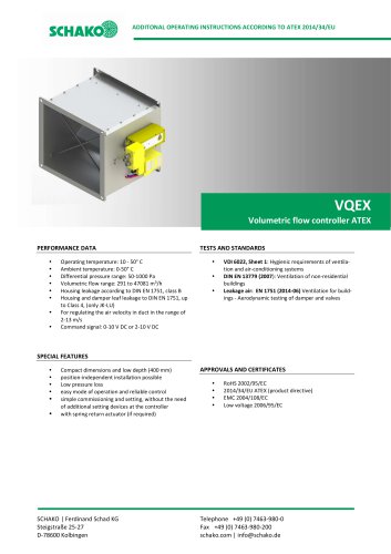 VQEX
VQEX17 Pages
 VPEX
VPEX18 Pages
 SVA-FS
11 Pages
 COMBIDSC
26 Pages
 DSC
DSC37 Pages
 DO
DO10 Pages
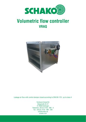 VRAQ
VRAQ46 Pages
 UEKU
UEKU6 Pages
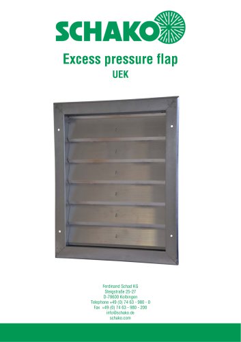 UEK
UEK6 Pages
 SS-K
SS-K6 Pages
 VOLKOM
6 Pages
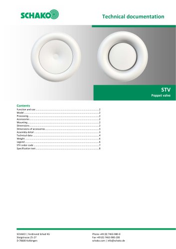 STV
STV8 Pages
 DQJ
DQJ38 Pages
 ALAS-F 125
6 Pages
 ALPETY
16 Pages
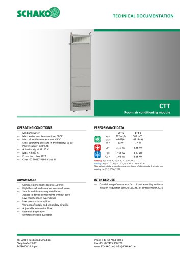 CTT
CTT23 Pages
 KWB
KWB19 Pages
 GREENKIT
20 Pages
 SVA-FF
15 Pages
 FKU
FKU31 Pages
 FKF
FKF29 Pages
 SGA
SGA5 Pages
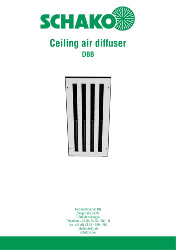 DBB
DBB27 Pages
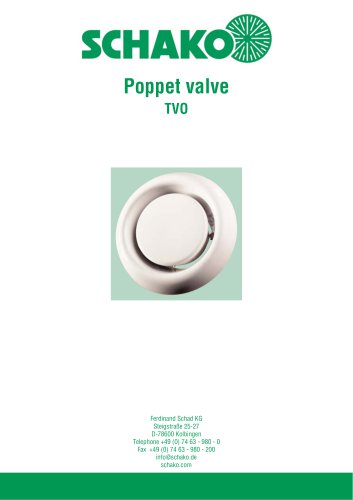 TVO
TVO8 Pages
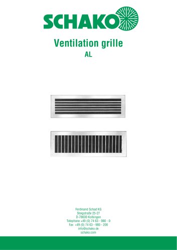 AL
AL23 Pages
 RF Return air filter grille
7 Pages
 NBS
NBS34 Pages
 MKAR_MKAQ
13 Pages
 KF
KF4 Pages
 JK
JK16 Pages
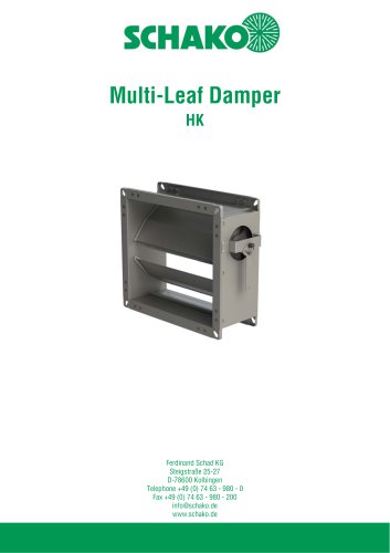 HK
HK16 Pages
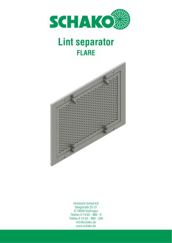 Lint Separator FLARE
13 Pages
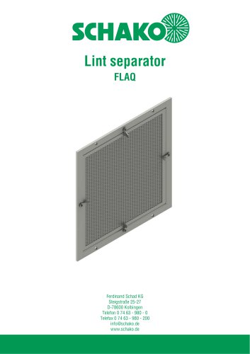 FLAQ
FLAQ11 Pages
 FG
FG14 Pages
 ERK-MB
38 Pages
 DISA-H (2025)
34 Pages
 DISA-360
32 Pages
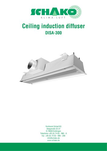 DISA-300
51 Pages
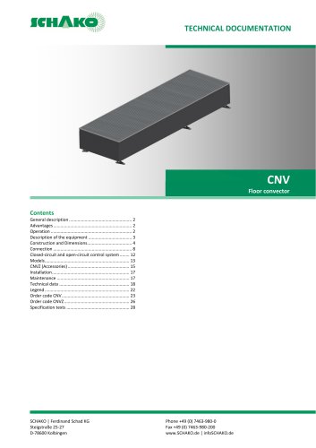 CNV
CNV29 Pages
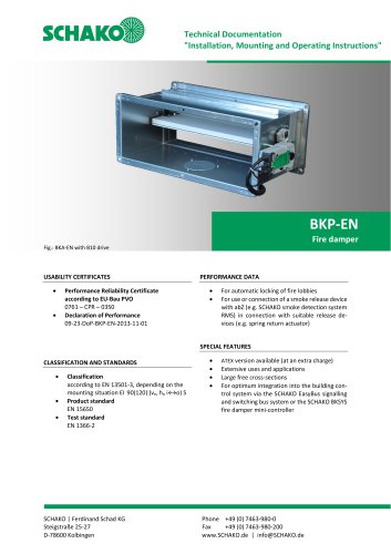
 BKP-EN Fire damper
40 Pages
 BKA-UE
35 Pages
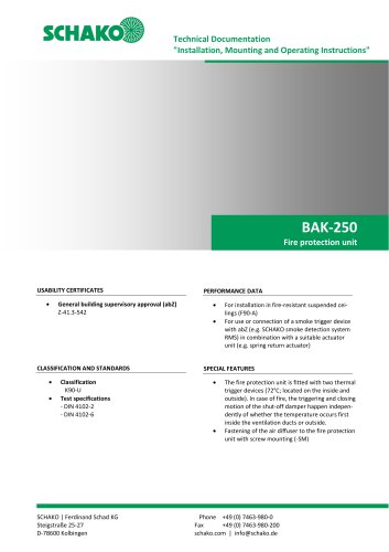 BAK-250 Fire protection unit
17 Pages
 BAK-240
16 Pages
 Aquaris-Silent
38 Pages
 Aquaris_KWB
20 Pages
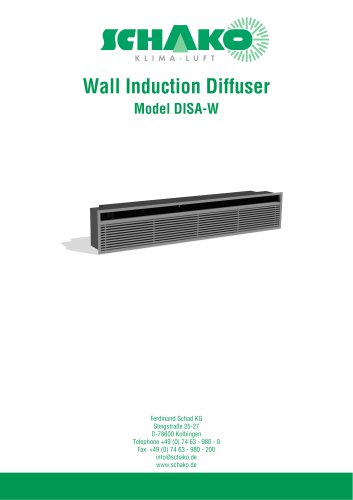 DISA-W
43 Pages
 CULTRA-Studioline
24 Pages
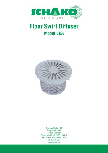 BDA
BDA11 Pages
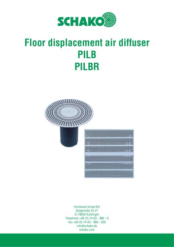 PILB/PILBR
33 Pages
 DAV
DAV19 Pages
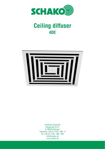 4DE
4DE18 Pages
 4DF
4DF13 Pages
 DQC
DQC16 Pages
 DQDL
DQDL16 Pages
 IDA
IDA21 Pages
 IKA
IKA23 Pages
 ZMD
ZMD17 Pages
 DQF
DQF15 Pages
 DQJF
DQJF12 Pages
 DQJA/DQJR
10 Pages
 DQJSL
DQJSL17 Pages
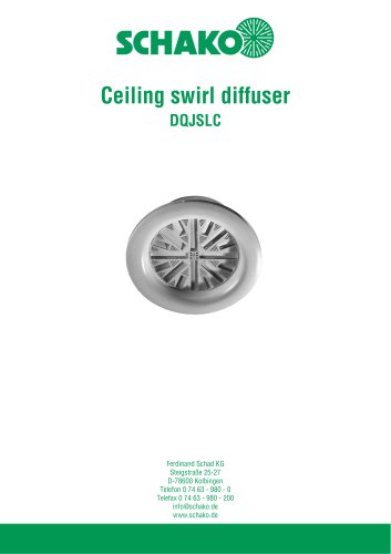 DQJSLC
17 Pages
 DHV
DHV18 Pages
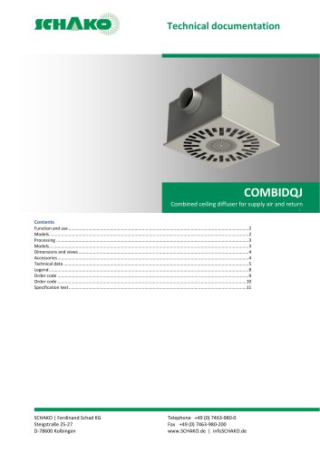 COMBIDQJ
11 Pages
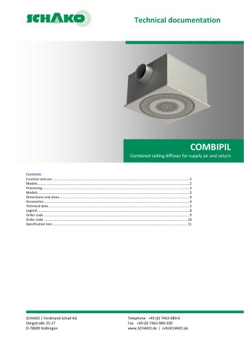 COMBIPIL
11 Pages
 DSA
DSA15 Pages
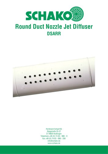 DSARR
DSARR7 Pages
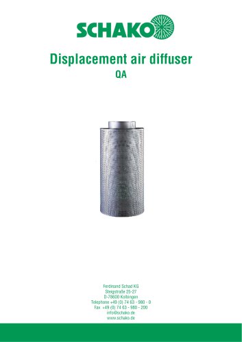 QA
QA30 Pages
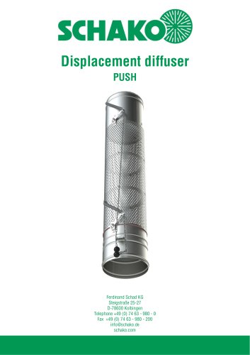 PUSH
PUSH23 Pages
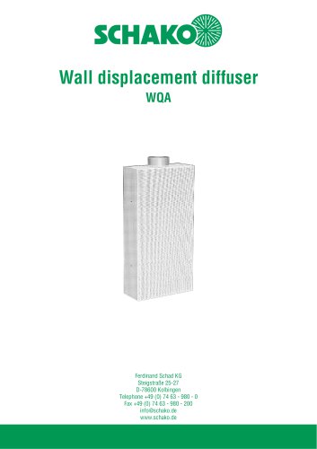 WQA
WQA12 Pages
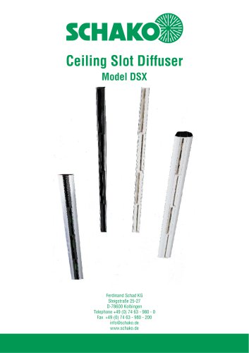 DSX
DSX25 Pages
 DSX-XXL
23 Pages
 AUDIX®-AW
20 Pages
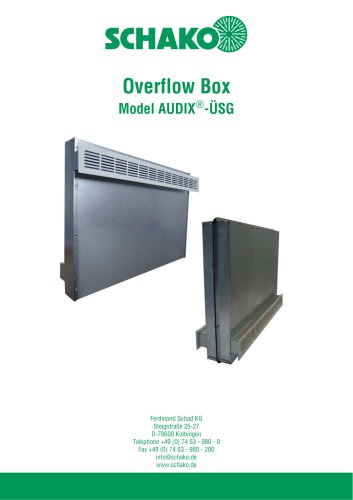 AUDIX®-ÜSG
13 Pages
 DSX-XXL-W
25 Pages
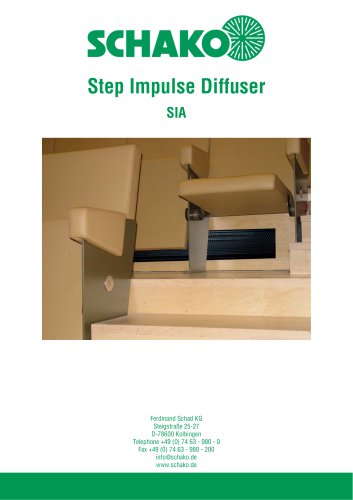 SIA
SIA7 Pages
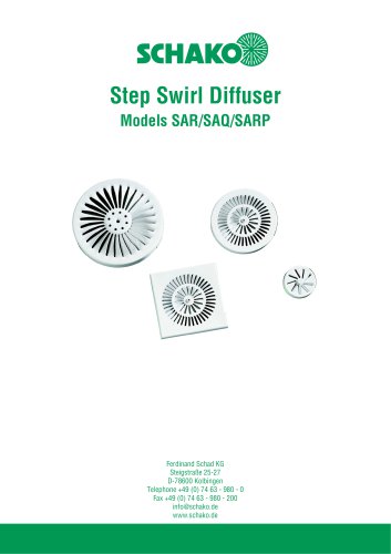 SAR/SAQ/SARP
13 Pages
 WDA
WDA32 Pages
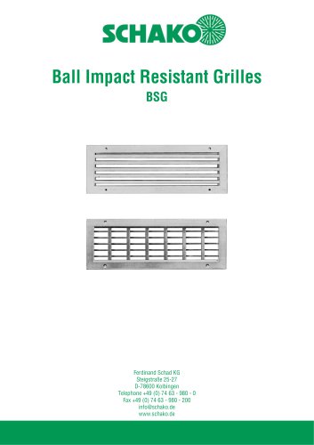 BSG
BSG19 Pages
 KG
KG19 Pages
 IB-Q
IB-Q21 Pages
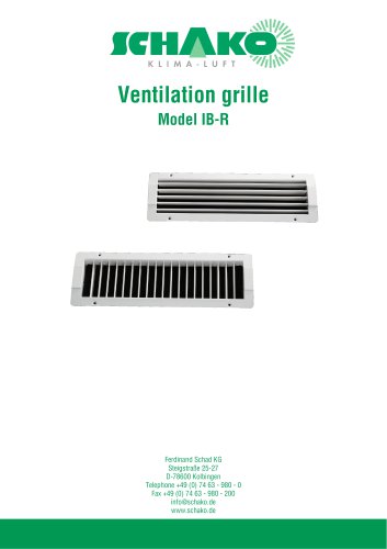 IB-R
IB-R15 Pages
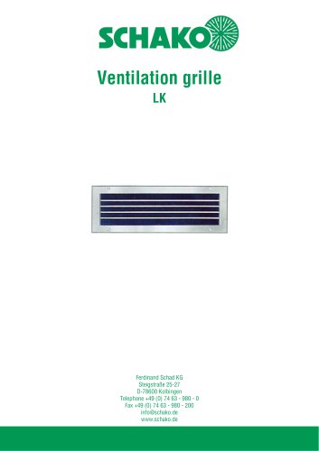 LK
LK12 Pages
 PA
PA32 Pages
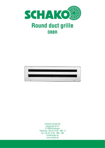 DBBR
DBBR6 Pages
 KGRR
KGRR17 Pages
 DBBRR
DBBRR11 Pages
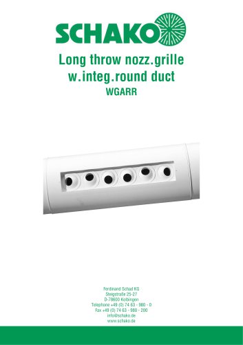 WGARR
WGARR7 Pages
 WGA
WGA29 Pages
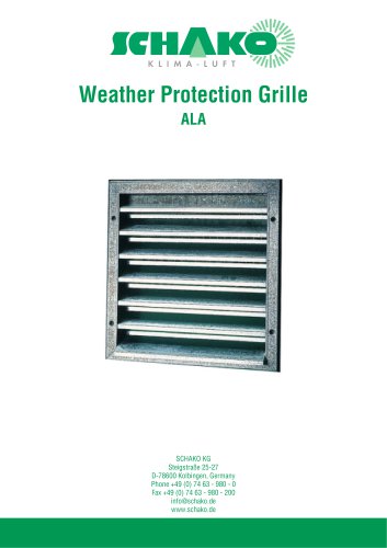 ALA
ALA4 Pages
 ALA-R
ALA-R4 Pages
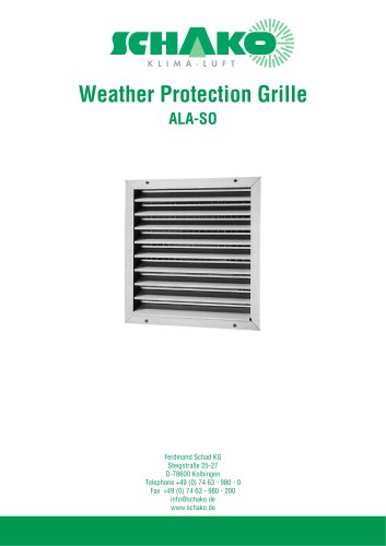 ALA-SO
4 Pages
 ALAS
ALAS10 Pages
 ALAS-P
5 Pages
 DKAPPs
6 Pages
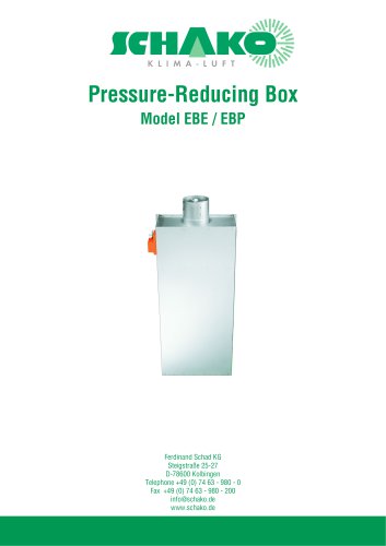 EBE/EBP
52 Pages
 DKG
DKG6 Pages
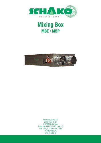 MBE/MBP
27 Pages
 PIANO
PIANO27 Pages
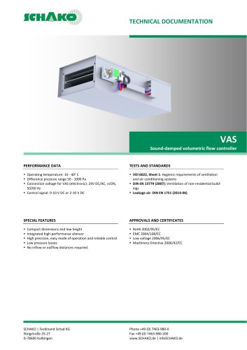 VAS
VAS26 Pages
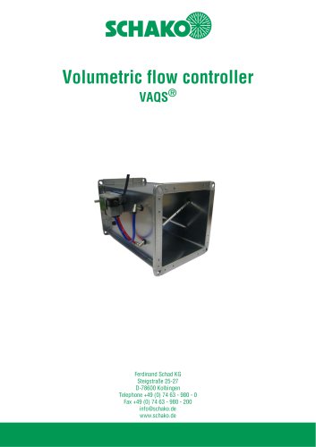 VAQS
VAQS19 Pages
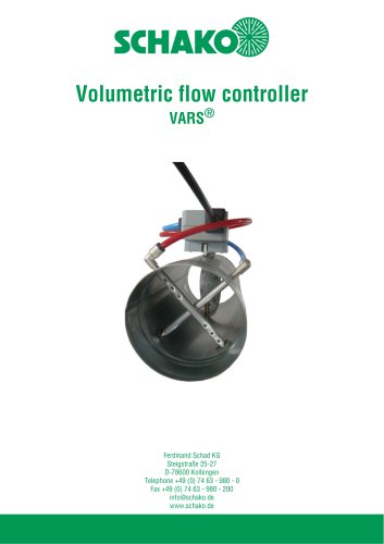 VARS
VARS26 Pages
 VRAPPs
20 Pages
 VRAR
VRAR52 Pages
 MAK
MAK15 Pages
 RS-F
RS-F7 Pages
 RS
RS15 Pages
 EasyBus
24 Pages
 DISA-Family
4 Pages
 RMS
RMS11 Pages
 TSR
TSR5 Pages
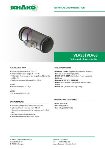 VLV
VLV31 Pages
 MBM
MBM10 Pages
 LL
LL7 Pages
 RR-Complete
41 Pages
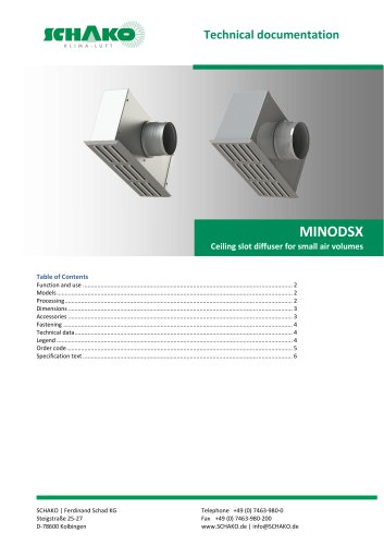 MINODSX
6 Pages
 SPB
SPB10 Pages
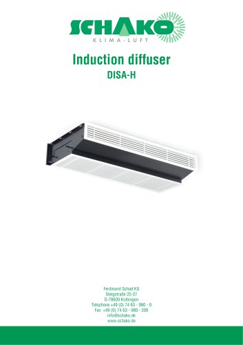 DISA-H
34 Pages
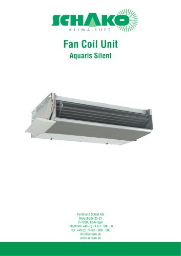 AQUARIS SILENT
38 Pages
 NBS
NBS24 Pages
 JK-LP/JK-LU
15 Pages
 HKP / HKU
16 Pages
 FKW
FKW16 Pages
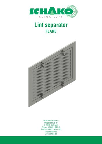 FLARE
FLARE13 Pages
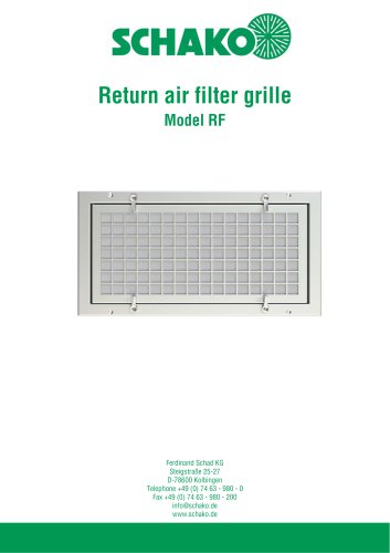 RF
RF7 Pages
 KGF
KGF9 Pages
 SVA-FF
8 Pages
 BKA-Ü
BKA-Ü35 Pages
 BSK-RPR
60 Pages
 BKP-EN
40 Pages
 BAK-240
6 Pages
 BAK-250
14 Pages


- Ventilation grill
- Industrial air conditioner
- Metal ventilation grill
- Rectangular ventilation grill
- Commercial detector
- Commercial air conditioning cabinet
- Industrial air diffuser
- Reversible air conditioner
- Aluminum ventilation grill
- Exterior ventilation grill
- Commercial ventilation grill
- Facade ventilation grill
- Ceiling-mounted air diffuser
- Industrial fan coil
- White ventilation grill
- Industrial convector
- Home ventilation grill
- Metal convector
- Contemporary convector
- Wall-mounted air conditioner