- Company
- Products
- Catalogs
- News & Trends
- Exhibitions
DSCU
1 /18Pages

DSCU
1 /18Pages
Catalog excerpts
Technical documentation DSCU Curved slot diffuser SCHAKO | Ferdinand Schad KG Steigstrasse 25-27 D-78600 Kolbingen
Open the catalog to page 1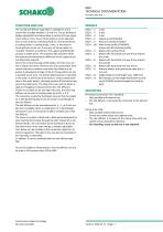
DSCU TECHNICAL DOCUMENTATION Function and use | MODELS DSCU-...-1 DSCU-...-2 DSCU-...-3 DSCU-...-Z DSCU-...-A DSCU-...-R0 DSCU-...-V DSCU-...-L DSCU-...-R DSCU-...-B DSCU-...-0 DSCU-...-N DSCU-...-B FUNCTION AND USE The curved slot diffuser type DSCU is suitable for use in rooms with a height between 2.6 and 4 m. The air deflection blades adjustable from below allow a variety of throw adjustment options. Thus, the air throw pattern can be adjusted from a vertical throw in heating mode to a horizontal throw in cooling mode. In cooling mode, a one- or two-way air throw pattern can be set. A one-way...
Open the catalog to page 2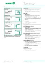
TECHNICAL DOCUMENTATION Blade position for air jet | Processing BLADE POSITION FOR AIR JET Blade position (-V) vertical throw PROCESSING Frame surface -- Natural colour anodised aluminium (-ELOX, standard). -- Painted aluminium: - RAL 9010 (white) (-9010). - To a different RAL colour (at an extra charge) (-xxxx). Blade colour Blade position (-B) with horizontal two-way throw -- Plastic (hard PVC): - Colour similar to RAL 9005 (black, standard) (-L9005). - Colour similar to RAL 9010 (white) (-L9010). - RAL colour can be freely selected (-Lxxxx) -- For return air without blade (-00000), with perforated...
Open the catalog to page 3
DSCU TECHNICAL DOCUMENTATION Accessories | Suspension: - Without riveting nut (-E0). - With riveting nut (-EM), made of brass. ACCESSORIES End pieces (-E0 / -ES / -EB / -EL / -ER) -- Without end pieces (-E0). -- With end pieces: - Supplied loose (-ES, pair) (standard). - Mounted ex works on both sides (-EB). - Mounted ex works on the left side (-EL). - Mounted ex works on the right side (-ER). Made of aluminium (same colour as frame). Dummy piece (-BS0 / -BS1) -- Without dummy piece (-BS0). -- With dummy piece (-BS1), made of sheet steel painted to RAL 9005 (black). - Only possible with clamp...
Open the catalog to page 4
DSCU TECHNICAL DOCUMENTATION Dimensions | Radius The radius R is always specified in the centre of the slot diffuser. R > 2000 (1- / 2- / 3-slot). * EOB = installation opening width For curved length distribution for slot diffuser, see page 6. In the return air model, a perforated plate is mounted instead of the air deflection blades. Construction subject to change No return possible
Open the catalog to page 5
TECHNICAL DOCUMENTATION Dimensions of accessories | Curved length distribution for slot diffuser - Curved length BoL= 1000 mm (-01000-N) - Curved length BoL= 1500 mm (-01500-N) - Curved length in mm, can be freely selected (-xxxxx-N) (Curved length BoL <1000 mm to ≥400 mm can be fitted with plenum box) = With inner lateral spigot (standard) = With outer lateral spigot - Inner lateral spigot (-S1) - Outer lateral spigot (-S2) Band design (-B) - Curved length in mm, can be freely selected, as band (-xxxxx-B) (curved length distribution according to SCHAKO standard lengths) For models with one spigot...
Open the catalog to page 6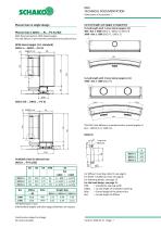
DSCU TECHNICAL DOCUMENTATION Dimensions of accessories | Curved length and spigot arrangement Plenum box (-AKCU-...-N-...-FV-S1/S2) With fixed connection. With lateral spigot. The slot diffuser is permanently connected to the plenum box. Detail X Available sizes for plenum box (AKCU-...-FV-S1/S2) *all dimensions in mm Intermediate lengths and other spigot diameters on request. For diffuser mounting, detail Z, see page 8. For detail Y (rubber lip seal), see page 8. For fastening details, see page 13. For the band design, see page 11. EOB = installation opening width EOBoL = curved length of installation...
Open the catalog to page 7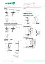
TECHNICAL DOCUMENTATION Dimensions of accessories | Rubber lip seal (-GD1), for AKCU with long hole ø6.5x10 (-E0, standard): M6 / on site on site Damper (-DK1), for AKCU Inner lateral spigot (-S1, standard) DSCU-1 DSCU-2 / DSCU-3 with riveting nut M4 (-EM, at an extra charge): At an extra charge, the plenum boxes can be fitted with M4 riveting nuts to facilitate ceiling mounting. Outer lateral spigot (-S2) DSCU-1 (only for 1-slot models) M4 / on site A Insulation (-la), for AKCU Outside (-la) Construction subject to change No return possible
Open the catalog to page 8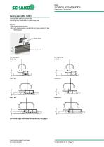
TECHNICAL DOCUMENTATION Dimensions of accessories | Dummy piece (-BS0 / -BS1) Only possible without plenum box. Mounting only possible with clamp strap (-KB). Models: -BS0: without dummy piece. -BS1: with dummy piece made of sheet steel painted to RAL 9005 (black). Clamp strap Dummy piece For curved length distribution for slot diffuser, see page 6. Construction subject to change No return possible
Open the catalog to page 9
TECHNICAL DOCUMENTATION Dimensions of accessories | End pieces (-E0 / -ES / -EB / -EL / -ER) To give the impression of a continuous frame, lateral front end pieces can be fitted. Detail W Without end piece (-E0) Models: -E0 = without end piece ES = with end pieces (pair), supplied loose as standard. -EB = with end pieces (pair) mounted ex works. EL = with end piece mounted ex works on the left side -ER = with end piece mounted ex works on the right side Curved length of installation opening: EÖBoL = BoL + 10 EÖBBoL = EÖBoL + 10 Please specify in your order whether end pieces are to be fitted...
Open the catalog to page 10
DSCU TECHNICAL DOCUMENTATION Plenum box in band design | Detail V Butt joint of permanent connection (-FV) When the slot diffuser type DSCU is designed as a band, the curved length of the band BBoL is assembled from sections (BoL) of 1000 mm or 1500 mm. The curved difference pieces <1500 mm to >400 mm can be fitted with a plenum box. The curved difference pieces < 400 mm are designed as dummy pieces without plenum box. A different band division is possible after consultation and when required by the customer. Installation opening EOB = see dimensions EOBoL = BoL+10 For detail W (end piece), see...
Open the catalog to page 11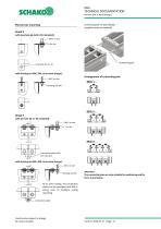
TECHNICAL DOCUMENTATION Plenum box in band design | Connecting pin for band design (supplied loose as standard) Plenum box mounting Detail X with long hole ø6.5x10 (-E0, standard): M6 / on site on site with riveting nut M4 (-EM, at an extra charge): Arrangement of connecting pins Detail Y with pin hole ø6.1 (-E0, standard): M6 / on site on site Connection plate with pin hole ø6.1 with riveting nut M4 (-EM, at an extra charge): M4 / on site Attention: The connecting pins are only suitable for positioning and for force transmission. At an extra charge, the connection plates can be provided with...
Open the catalog to page 12All SCHAKO KG catalogs and technical brochures
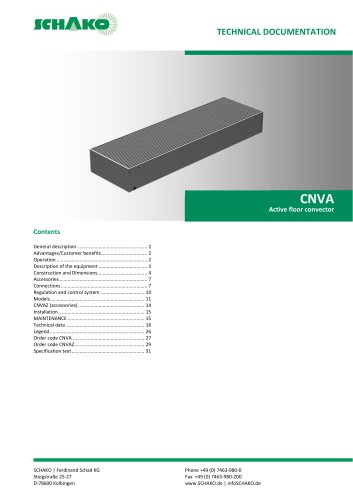 CNVA
CNVA32 Pages
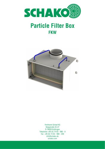 FKW (2025)
28 Pages
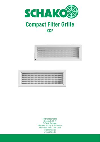 KGF Compact Filter Grille
9 Pages
 AUDIX
AUDIX2 Pages
 DISA
DISA4 Pages
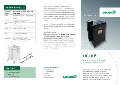 UC-OH²
2 Pages
 IGA
IGA2 Pages
 CDD
CDD2 Pages
 FBS
FBS18 Pages
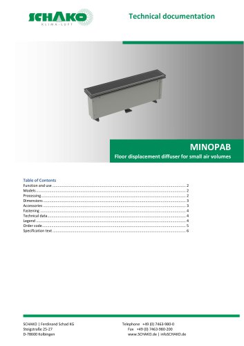 MINOPAB (2025)
6 Pages
 PIL
PIL23 Pages
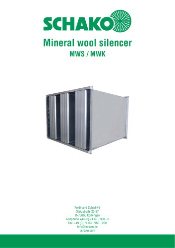 MWS / MWK
23 Pages
 ERK-SO
43 Pages
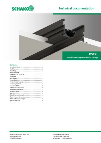 DSCXL
DSCXL17 Pages
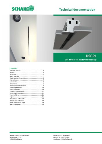 DSCPL
DSCPL16 Pages
 BKSYS
BKSYS18 Pages
 MINODSA
6 Pages
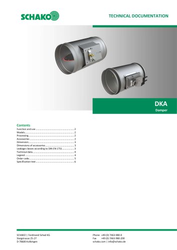 DKA
DKA6 Pages
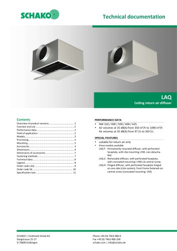 LAQ
LAQ11 Pages
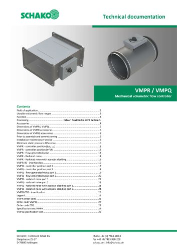 VMPR/VMPQ
29 Pages
 DSCP
DSCP15 Pages
 DQJP
DQJP9 Pages
 BKA-EN
79 Pages
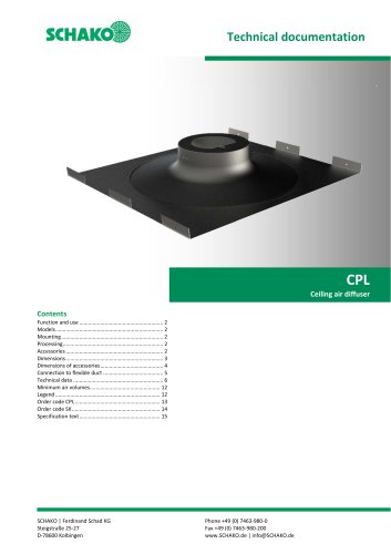 CPL
CPL15 Pages
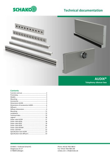 AUDIX®
25 Pages
 VREX
VREX26 Pages
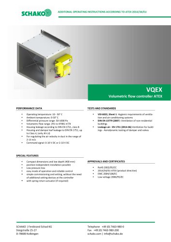 VQEX
VQEX17 Pages
 VPEX
VPEX18 Pages
 SVA-FS
11 Pages
 NRWG
NRWG22 Pages
 COMBIDSC
26 Pages
 DSC
DSC37 Pages
 DO
DO10 Pages
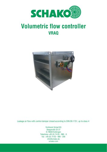 VRAQ
VRAQ46 Pages
 UEKU
UEKU6 Pages
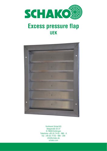 UEK
UEK6 Pages
 SS-K
SS-K6 Pages
 VOLKOM
6 Pages
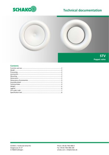 STV
STV8 Pages
 DQJ
DQJ38 Pages
 ALAS-F 125
6 Pages
 ALPETY
16 Pages
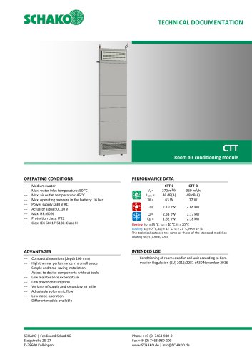 CTT
CTT23 Pages
 KWB
KWB19 Pages
 GREENKIT
20 Pages
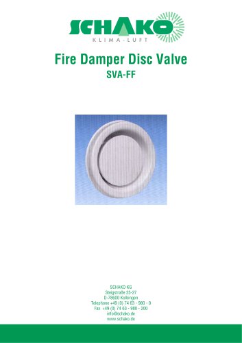
 SVA-FF
15 Pages
 FKU
FKU31 Pages
 FKF
FKF29 Pages
 SGA
SGA5 Pages
 DBB
DBB27 Pages
 TVO
TVO8 Pages
 AL
AL23 Pages
 RF Return air filter grille
7 Pages
 NBS
NBS34 Pages
 MKAR_MKAQ
13 Pages
 KF
KF4 Pages
 JK
JK16 Pages
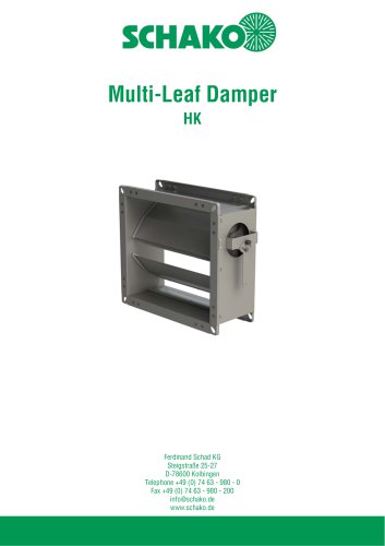 HK
HK16 Pages
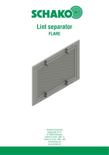 Lint Separator FLARE
13 Pages
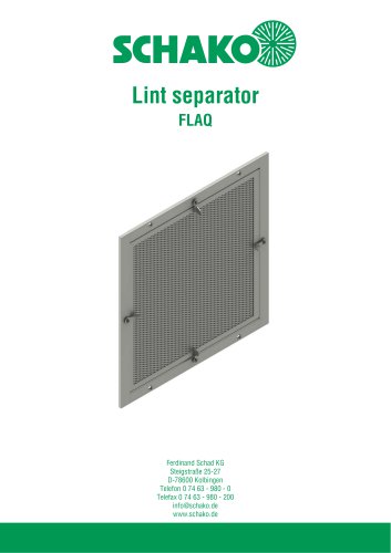 FLAQ
FLAQ11 Pages
 FG
FG14 Pages
 ERK-MB
38 Pages
 DISA-H (2025)
34 Pages
 DISA-360
32 Pages
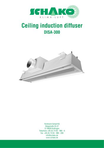 DISA-300
51 Pages
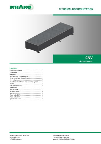 CNV
CNV29 Pages
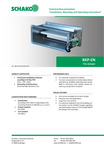
 BKP-EN Fire damper
40 Pages
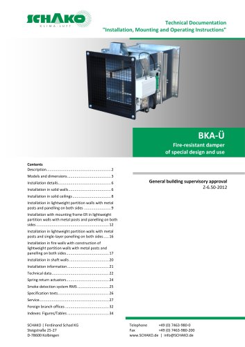 BKA-UE
35 Pages
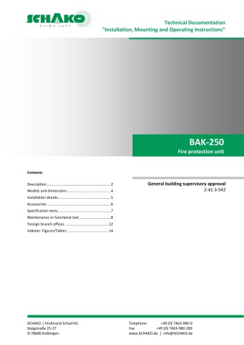
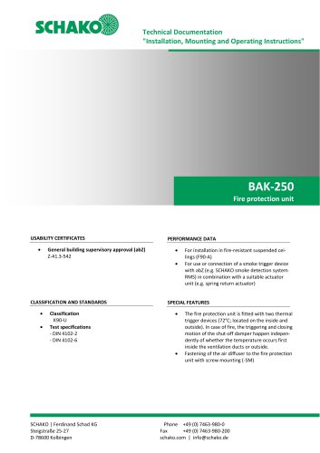 BAK-250 Fire protection unit
17 Pages
 BAK-240
16 Pages
 Aquaris-Silent
38 Pages
 Aquaris_KWB
20 Pages
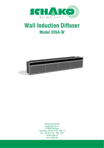 DISA-W
43 Pages
 CULTRA-Studioline
24 Pages
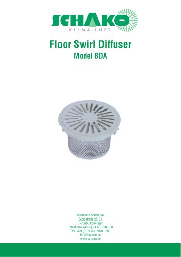 BDA
BDA11 Pages
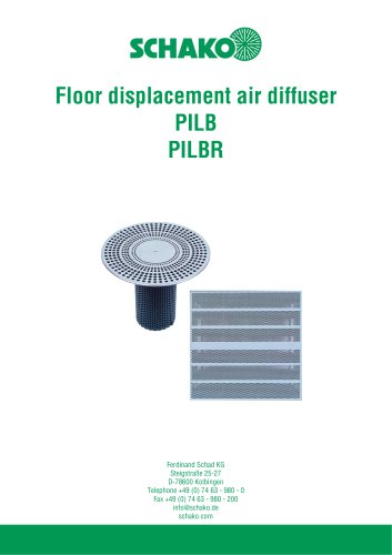 PILB/PILBR
33 Pages
 DAV
DAV19 Pages
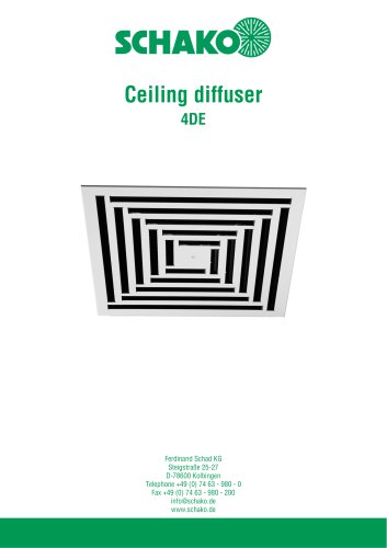 4DE
4DE18 Pages
 4DF
4DF13 Pages
 DQC
DQC16 Pages
 DQDL
DQDL16 Pages
 IDA
IDA21 Pages
 IKA
IKA23 Pages
 ZMD
ZMD17 Pages
 DQF
DQF15 Pages
 DQJF
DQJF12 Pages
 DQJA/DQJR
10 Pages
 DQJSL
DQJSL17 Pages
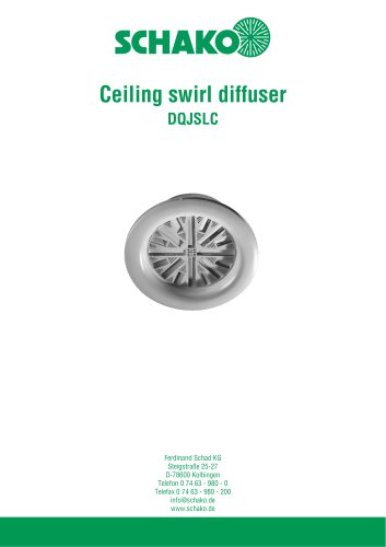 DQJSLC
17 Pages
 DHV
DHV18 Pages
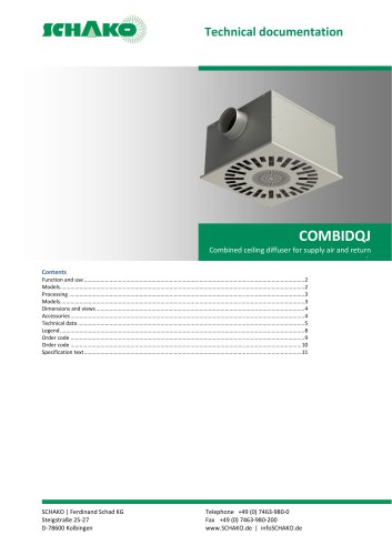 COMBIDQJ
11 Pages
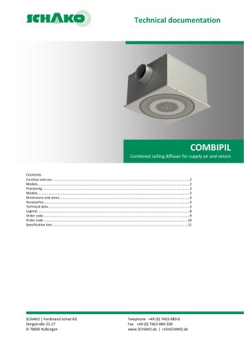 COMBIPIL
11 Pages
 DSA
DSA15 Pages
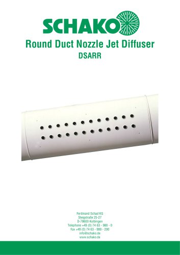 DSARR
DSARR7 Pages
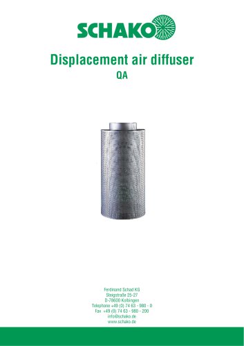 QA
QA30 Pages
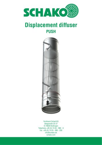 PUSH
PUSH23 Pages
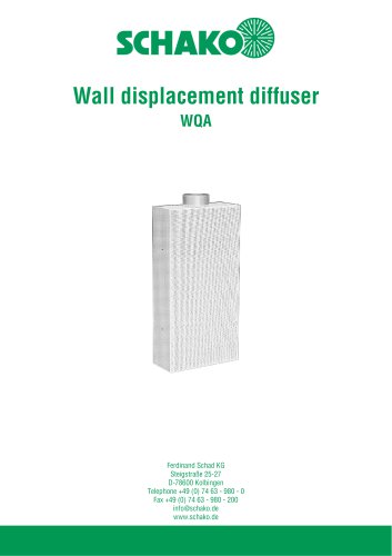 WQA
WQA12 Pages
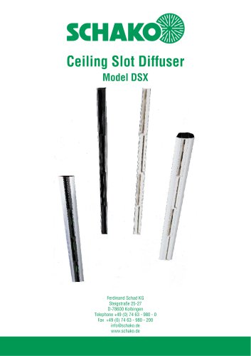 DSX
DSX25 Pages
 DSX-XXL
23 Pages
 AUDIX®-AW
20 Pages
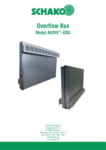 AUDIX®-ÜSG
13 Pages
 DSX-XXL-W
25 Pages
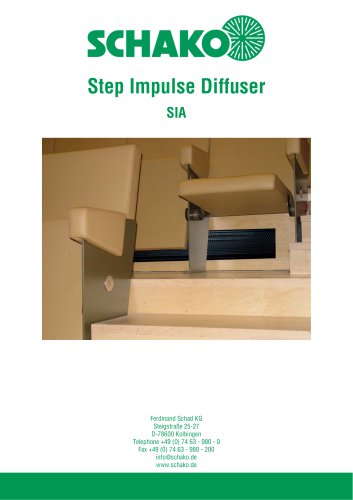 SIA
SIA7 Pages
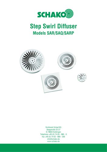 SAR/SAQ/SARP
13 Pages
 WDA
WDA32 Pages
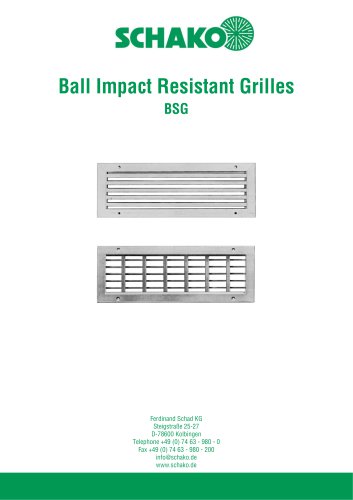 BSG
BSG19 Pages
 KG
KG19 Pages
 IB-Q
IB-Q21 Pages
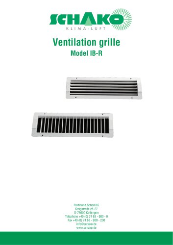 IB-R
IB-R15 Pages
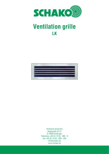 LK
LK12 Pages
 PA
PA32 Pages
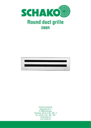 DBBR
DBBR6 Pages
 KGRR
KGRR17 Pages
 DBBRR
DBBRR11 Pages
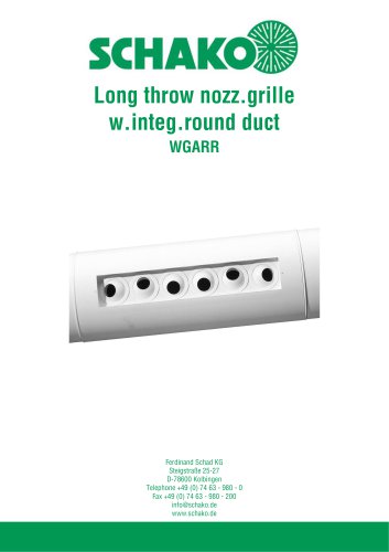 WGARR
WGARR7 Pages
 WGA
WGA29 Pages
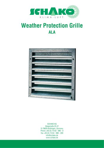 ALA
ALA4 Pages
 ALA-R
ALA-R4 Pages
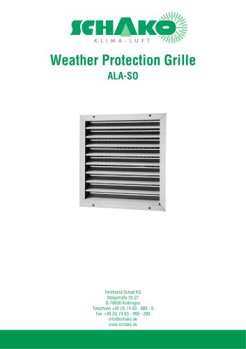 ALA-SO
4 Pages
 ALAS
ALAS10 Pages
 ALAS-P
5 Pages
 DKAPPs
6 Pages
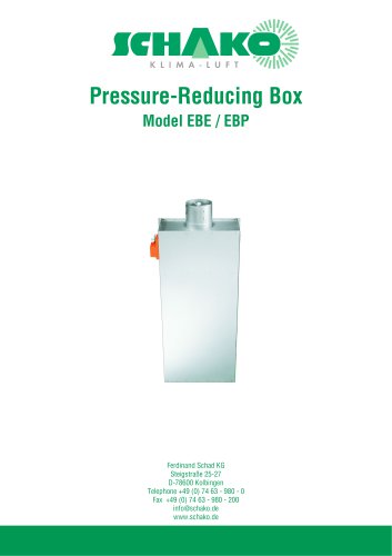 EBE/EBP
52 Pages
 DKG
DKG6 Pages
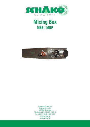 MBE/MBP
27 Pages
 PIANO
PIANO27 Pages
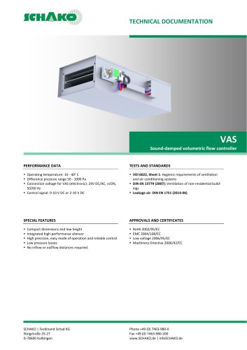 VAS
VAS26 Pages
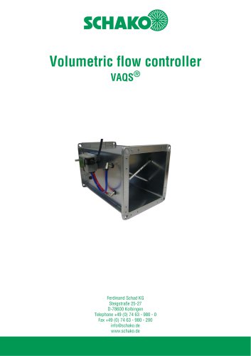 VAQS
VAQS19 Pages
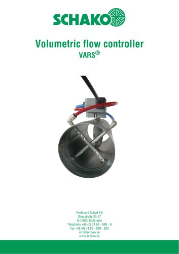 VARS
VARS26 Pages
 VRAPPs
20 Pages
 VRAR
VRAR52 Pages
 MAK
MAK15 Pages
 RS-F
RS-F7 Pages
 RS
RS15 Pages
 EasyBus
24 Pages
 DISA-Family
4 Pages
 RMS
RMS11 Pages
 TSR
TSR5 Pages
 VLV
VLV31 Pages
 MBM
MBM10 Pages
 LL
LL7 Pages
 RR-Complete
41 Pages
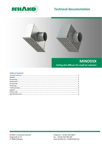 MINODSX
6 Pages
 SPB
SPB10 Pages
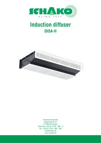 DISA-H
34 Pages
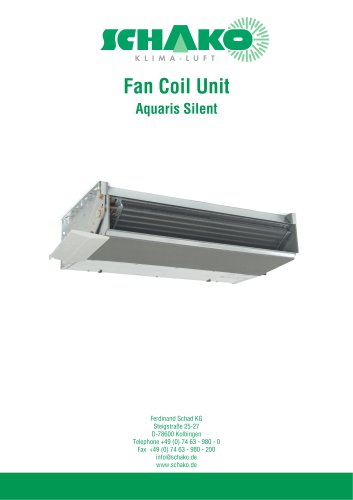 AQUARIS SILENT
38 Pages
 NBS
NBS24 Pages
 JK-LP/JK-LU
15 Pages
 HKP / HKU
16 Pages
 FKW
FKW16 Pages
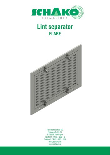 FLARE
FLARE13 Pages
 RF
RF7 Pages
 KGF
KGF9 Pages
 SVA-FF
8 Pages
 BKA-Ü
BKA-Ü35 Pages
 BSK-RPR
60 Pages
 BKP-EN
40 Pages
 BAK-240
6 Pages
 BAK-250
14 Pages


- Ventilation grill
- Industrial air conditioner
- Metal ventilation grill
- Rectangular ventilation grill
- Commercial detector
- Commercial air conditioning cabinet
- Industrial air diffuser
- Reversible air conditioner
- Aluminum ventilation grill
- Exterior ventilation grill
- Commercial ventilation grill
- Facade ventilation grill
- Ceiling-mounted air diffuser
- Industrial fan coil
- White ventilation grill
- Industrial convector
- Home ventilation grill
- Metal convector
- Contemporary convector
- Wall-mounted air conditioner