- Company
- Products
- Catalogs
- News & Trends
- Exhibitions
CNVA
1 /32Pages
CNVA
1 /32Pages
Catalog excerpts
TECHNICAL DOCUMENTATION SCHAKO | Ferdinand Schad KG Steigstraße 25-27 D-78600 Kolbingen
Open the catalog to page 1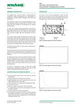
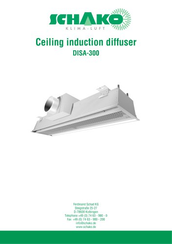
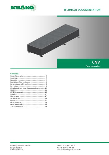
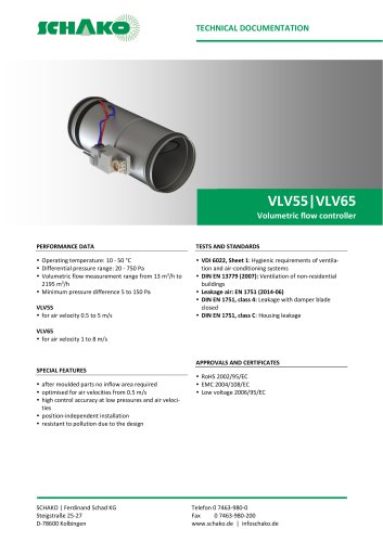
TECHNICAL DOCUMENTATION General description | Advantages/Customer benefits | Operation GENERAL DESCRIPTION The SCHAKO floor convectors CNVA as decentralised airconditioners enable energy-efficient and comfortable airconditioning of offices, public buildings, sales rooms and living spaces. The room air (1) to be air-conditioned is taken into the convector by the fan (4) via the slip-resistant grille and the filter, cooled or heated via the heat exchanger (3) and supplied again to the room (2) via the tread-resistant grille. The CNVA floor convectors are particularly suitable for rooms with large...
Open the catalog to page 2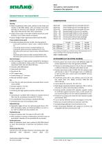
TECHNICAL DOCUMENTATION Description of the equipment DESCRIPTION OF THE EQUIPMENT MODELS Housing • Made of galvanised sheet steel, painted on the inside and outside to RAL 9005 (black), with pre-marked connection openings for electrical and hydraulic connections on the right (-W2/-W4) and left (-W1/-W3), respectively. • Upper frame made of extruded anodised aluminium profiles E6/Ev1 (-G1). Other colours on request. • Spacer bridges made of galvanised sheet steel RAL 9005. Tread-resistant louvre grid • Extruded anodised aluminium profile. Painting optional: - Linear grille aluminium natural colour...
Open the catalog to page 3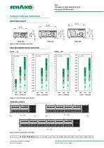
TECHNICAL DOCUMENTATION Construction and Dimensions CONSTRUCTION AND DIMENSIONS WIDTH AND HEIGHT Figure 4: Width and Height of the CNVA HEAT EXCHANGER QUICK SELECTION CNVA-…-H2 Diagram 1: Heat exchanger quick selection NOMINAL LENGTH Figure 5: Nominal length (NL) of the CNVA
Open the catalog to page 4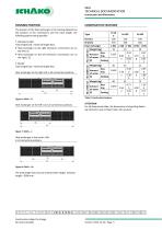
TECHNICAL DOCUMENTATION Construction and Dimensions 2. Model Total length (LG) > Nominal length (NL) Heat exchanger on the right (-R) in all connection positions. Heat exchanger on the left (-L) in all connection positions. H (mm) W (mm) Heat exchanger Weight (kg) HeaAmount ting of water (l) Cooling NL=1150 mm 1. Standard model Total length (LG) = Nominal length (NL): • Heat exchanger on the right whenever connections are on the left (-S). • Heat exchanger on the left whenever connections are on the right (-S). The position of the heat exchanger in the housing depends on the position of the connections...
Open the catalog to page 5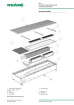
TECHNICAL DOCUMENTATION Construction and Dimensions EXPLODED DRAWING 1. Tread-resistant louvre grid 2. Spacer bridges 7. EC fan 3. Filter 4. Filter frame 5. Cover plate 6. Heat exchanger 8. Junction box 9. Housing 10. Adjustable legs Figure 9: Exploded drawing of the CNVA Construction subject to change No return possible
Open the catalog to page 6
TECHNICAL DOCUMENTATION Accessories │ Connections PRIMARY AIR CONNECTING PIECE Additional connecting piece for primary air entry with air diffuser plate (connection to room side). 3 1 Figure 13: Primary air connection pipe for CNVA Primary air connecting piece position • Without primary air connecting piece (-0) • Lateral left primary air connecting piece (-1) • Lateral right primary air connecting piece (-2) • Primary air connecting piece left front side (room side) (-3) • Primary air connecting piece right front side (room side) (4) • Primary air connecting piece centre dummy piece (-5) • Two...
Open the catalog to page 7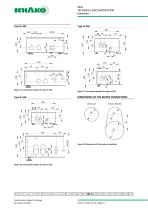
TECHNICAL DOCUMENTATION Connections Figure 15: Connection position for type H=106 Figure 17: Connection position for type H=190 DIMENSIONS OF THE WATER CONNECTIONS Figure 18: Dimensions of the water connections Figure 16: Connection position for type H=150
Open the catalog to page 8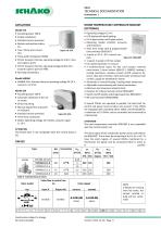
TECHNICAL DOCUMENTATION Connections | ROOM TEMPERATURE CONTROLLER RDG160T (OPTIONAL) ACTUATORS Model STA • Actuating power 100 N. • Simple installation. • Standard version prewired. • Motion and position indicator. • Two-/ three-wire connecFigure 19: STA tion. • Pulse width modulation (PDM). • STA23: Actuator thermal, operating voltage AC 230 V, actuator signal 2-point. • STA73: Actuator thermal, operating voltage AC/DC 24 V, actuator signal 2-point or PDM. • Normally Closed (NC). Model SABNM • SABNM-LOG: Actuator thermal, operating voltage DC 24 V, control 0...10 V DC. Model SSA • Actuating...
Open the catalog to page 9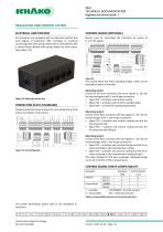
TECHNICAL DOCUMENTATION Regulation and control system | REGULATION AND CONTROL SYSTEM ELECTRICAL JUNCTION BOX CONTROL BOARD (OPTIONAL) All convectors are equipped with an electrical junction box with degree of protection IP65, including an electrical connecting plate with spring clamps (-S0) or alternatively with a control board likewise with spring clamps for three operating modes (-S1) Electric card for controlling the convector by means of 0...10 V DC signals. The control board has three operating modes, which can be selected by means of switches. Figure 22: Electrical junction box CONNECTING...
Open the catalog to page 10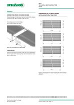
TECHNICAL DOCUMENTATION Models MODELS CONNECTING PIECE FOR BAND DESIGN DIMENSIONS OF THE GRILLE INSERT WITH AND WITHOUT END PIECE Figure 25: Connecting piece for band design Thermal and acoustic insulation made of 3-mm polyethylene on the outside of the housing (-A3). Recommended for installation in false floors. Connecting pieces for band design. At the ends without end pieces Possible design with end piece on both sides (-E2), without end piece (-E0), right only (-ER) or left only (-EL). Figure 26: Total length of the tread-resistant grilles with or without end piece
Open the catalog to page 11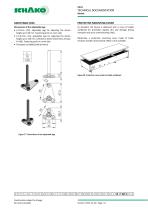
TECHNICAL DOCUMENTATION Models ADJUSTABLE LEGS PROTECTIVE MOUNTING COVER Dimensions of the adjustable legs • L=70 mm (-07), adjustable legs for adjusting the device height up to 60 mm. Fastening point on room side. • L=130 mm (-13), adjustable legs for adjusting the device height up to 120 mm. (Limited to device dimensions of type H=106). Fastening point on room side. • Threaded rod DIN913 M8 (S=4mm) As standard, the device is delivered with a cover of stable cardboard for protection against dirt and damage during transport and up to commissioning (-M1). Optionally, a protective mounting cover...
Open the catalog to page 12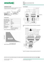
TECHNICAL DOCUMENTATION Models Circuit diagram CONDENSATE PUMP Pump and small sensor housing for emptying the water of condensation formed in the cooling register. Drain Float block Condensate pan Condensate pump Figure 29: Condensate pump Technical data Max. delivery rate Max. delivery height Maximum pressure Electric power Power supply Alarm Overheating protection operating ratio Protection class Dimensions 15 l/h 2m 10 m 19 W 220-240 V NO/NC 5 A 70 °C 100% IP64 Pump block: 85x28x48 mm Float block: 78x38x37 mm Figure 31: Circuit diagram of condensate pump with connecting plate (S0) Table 7:...
Open the catalog to page 13All SCHAKO KG catalogs and technical brochures
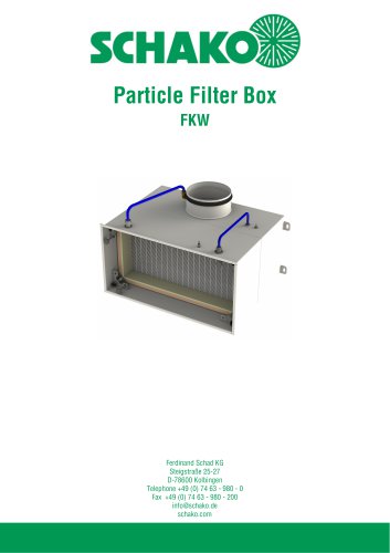 FKW (2025)
28 Pages
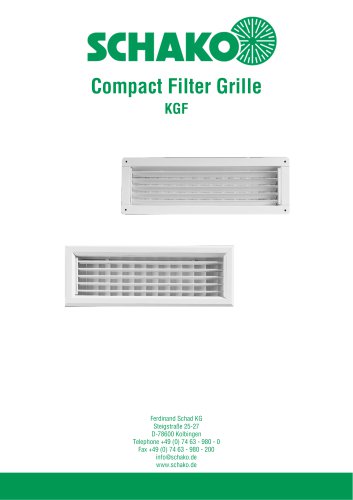 KGF Compact Filter Grille
9 Pages
 AUDIX
AUDIX2 Pages
 DISA
DISA4 Pages
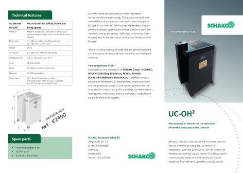 UC-OH²
2 Pages
 IGA
IGA2 Pages
 CDD
CDD2 Pages
 FBS
FBS18 Pages
 MINOPAB (2025)
6 Pages
 PIL
PIL23 Pages
 MWS / MWK
23 Pages
 ERK-SO
43 Pages
 DSCXL
DSCXL17 Pages
 DSCPL
DSCPL16 Pages
 BKSYS
BKSYS18 Pages
 MINODSA
6 Pages
 DKA
DKA6 Pages
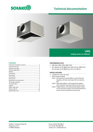 LAQ
LAQ11 Pages
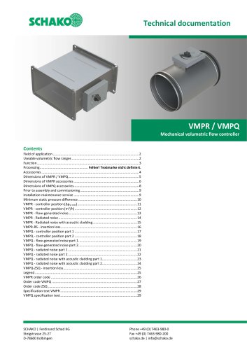 VMPR/VMPQ
29 Pages
 DSCU
DSCU18 Pages
 DSCP
DSCP15 Pages
 DQJP
DQJP9 Pages
 BKA-EN
79 Pages
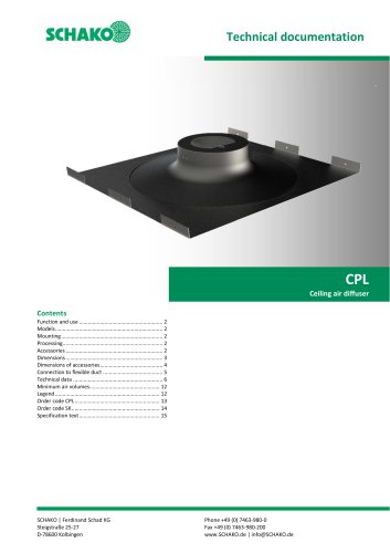 CPL
CPL15 Pages
 AUDIX®
25 Pages
 VREX
VREX26 Pages
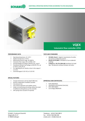 VQEX
VQEX17 Pages
 VPEX
VPEX18 Pages
 SVA-FS
11 Pages
 NRWG
NRWG22 Pages
 COMBIDSC
26 Pages
 DSC
DSC37 Pages
 DO
DO10 Pages
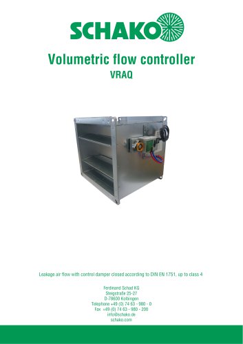 VRAQ
VRAQ46 Pages
 UEKU
UEKU6 Pages
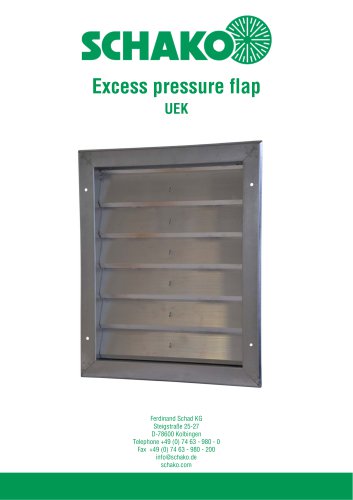 UEK
UEK6 Pages
 SS-K
SS-K6 Pages
 VOLKOM
6 Pages
 STV
STV8 Pages
 DQJ
DQJ38 Pages
 ALAS-F 125
6 Pages
 ALPETY
16 Pages
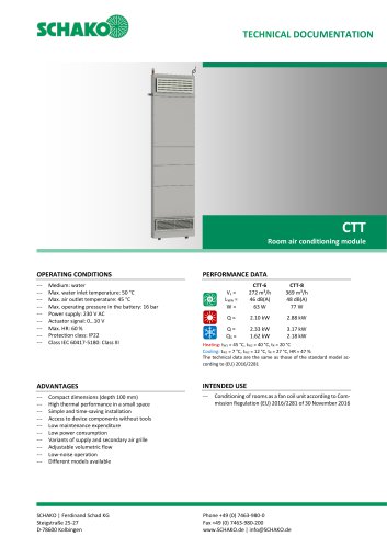 CTT
CTT23 Pages
 KWB
KWB19 Pages
 GREENKIT
20 Pages
 SVA-FF
15 Pages
 FKU
FKU31 Pages
 FKF
FKF29 Pages
 SGA
SGA5 Pages
 DBB
DBB27 Pages
 TVO
TVO8 Pages
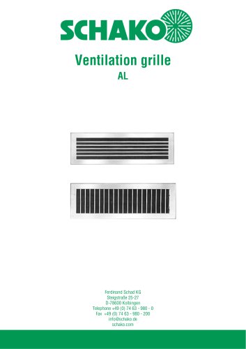 AL
AL23 Pages
 RF Return air filter grille
7 Pages
 NBS
NBS34 Pages
 MKAR_MKAQ
13 Pages
 KF
KF4 Pages
 JK
JK16 Pages
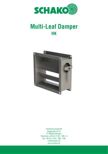 HK
HK16 Pages
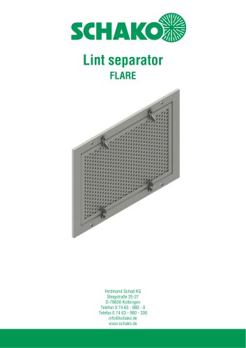 Lint Separator FLARE
13 Pages
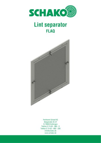 FLAQ
FLAQ11 Pages
 FG
FG14 Pages
 ERK-MB
38 Pages
 DISA-H (2025)
34 Pages
 DISA-360
32 Pages
 DISA-300
51 Pages
 CNV
CNV29 Pages
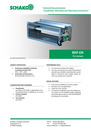
 BKP-EN Fire damper
40 Pages
 BKA-UE
35 Pages
 BAK-250 Fire protection unit
17 Pages
 BAK-240
16 Pages
 Aquaris-Silent
38 Pages
 Aquaris_KWB
20 Pages
 DISA-W
43 Pages
 CULTRA-Studioline
24 Pages
 BDA
BDA11 Pages
 PILB/PILBR
33 Pages
 DAV
DAV19 Pages
 4DE
4DE18 Pages
 4DF
4DF13 Pages
 DQC
DQC16 Pages
 DQDL
DQDL16 Pages
 IDA
IDA21 Pages
 IKA
IKA23 Pages
 ZMD
ZMD17 Pages
 DQF
DQF15 Pages
 DQJF
DQJF12 Pages
 DQJA/DQJR
10 Pages
 DQJSL
DQJSL17 Pages
 DQJSLC
17 Pages
 DHV
DHV18 Pages
 COMBIDQJ
11 Pages
 COMBIPIL
11 Pages
 DSA
DSA15 Pages
 DSARR
DSARR7 Pages
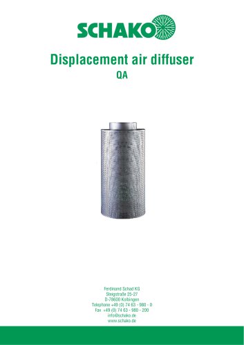 QA
QA30 Pages
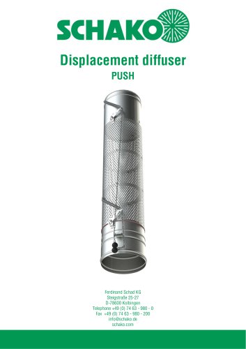 PUSH
PUSH23 Pages
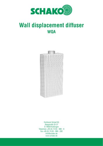 WQA
WQA12 Pages
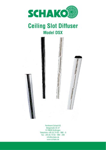 DSX
DSX25 Pages
 DSX-XXL
23 Pages
 AUDIX®-AW
20 Pages
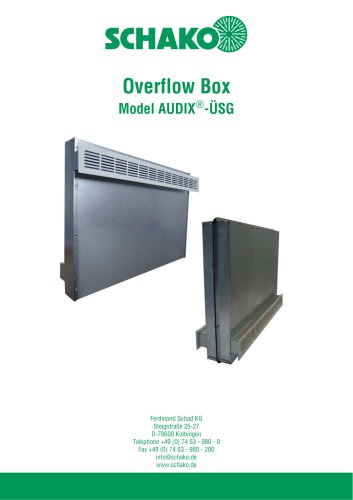 AUDIX®-ÜSG
13 Pages
 DSX-XXL-W
25 Pages
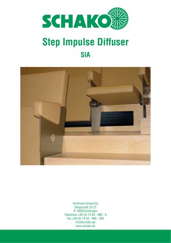 SIA
SIA7 Pages
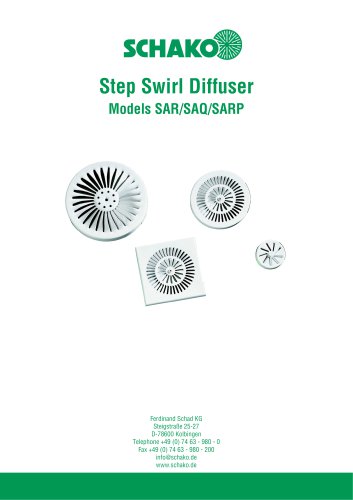 SAR/SAQ/SARP
13 Pages
 WDA
WDA32 Pages
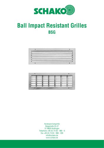 BSG
BSG19 Pages
 KG
KG19 Pages
 IB-Q
IB-Q21 Pages
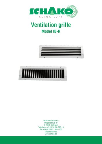 IB-R
IB-R15 Pages
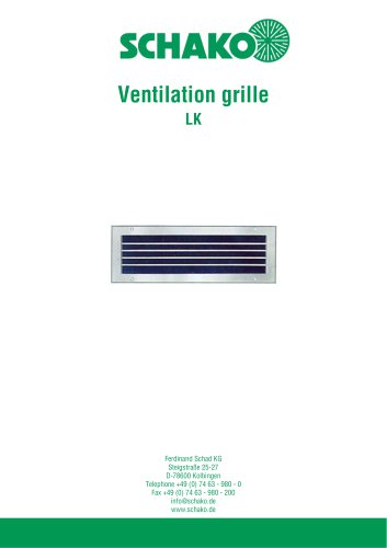 LK
LK12 Pages
 PA
PA32 Pages
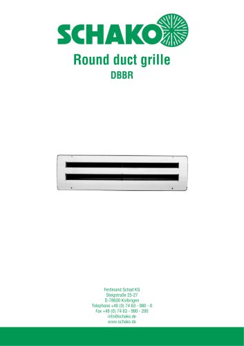 DBBR
DBBR6 Pages
 KGRR
KGRR17 Pages
 DBBRR
DBBRR11 Pages
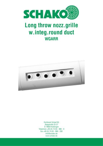 WGARR
WGARR7 Pages
 WGA
WGA29 Pages
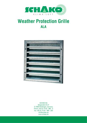 ALA
ALA4 Pages
 ALA-R
ALA-R4 Pages
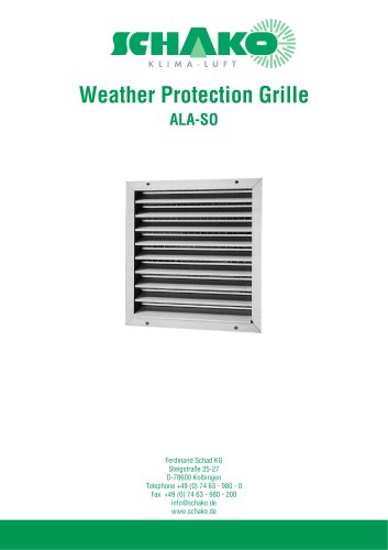 ALA-SO
4 Pages
 ALAS
ALAS10 Pages
 ALAS-P
5 Pages
 DKAPPs
6 Pages
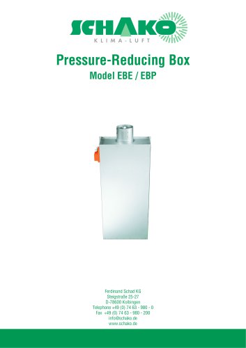 EBE/EBP
52 Pages
 DKG
DKG6 Pages
 MBE/MBP
27 Pages
 PIANO
PIANO27 Pages
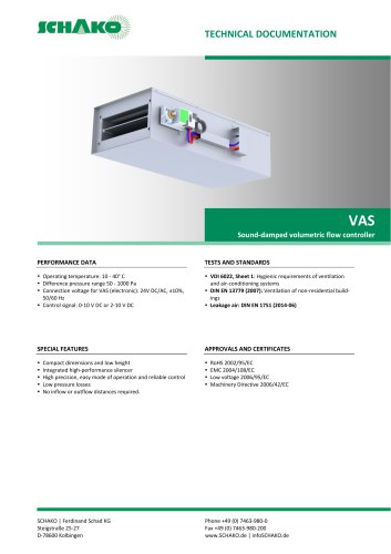 VAS
VAS26 Pages
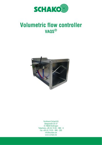 VAQS
VAQS19 Pages
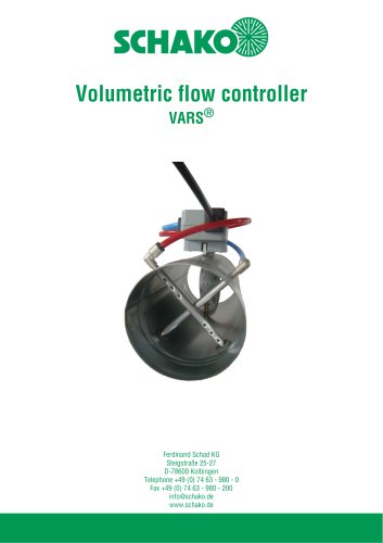 VARS
VARS26 Pages
 VRAPPs
20 Pages
 VRAR
VRAR52 Pages
 MAK
MAK15 Pages
 RS-F
RS-F7 Pages
 RS
RS15 Pages
 EasyBus
24 Pages
 DISA-Family
4 Pages
 RMS
RMS11 Pages
 TSR
TSR5 Pages
 VLV
VLV31 Pages
 MBM
MBM10 Pages
 LL
LL7 Pages
 RR-Complete
41 Pages
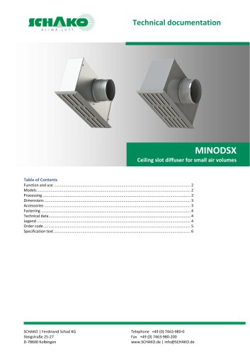 MINODSX
6 Pages
 SPB
SPB10 Pages
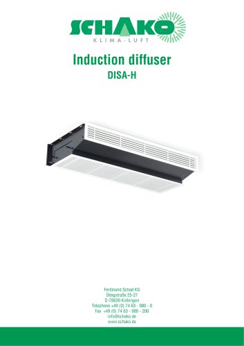 DISA-H
34 Pages
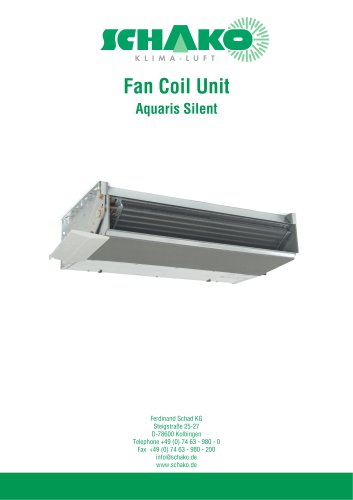 AQUARIS SILENT
38 Pages
 NBS
NBS24 Pages
 JK-LP/JK-LU
15 Pages
 HKP / HKU
16 Pages
 FKW
FKW16 Pages
 FLARE
FLARE13 Pages
 RF
RF7 Pages
 KGF
KGF9 Pages
 SVA-FF
8 Pages
 BKA-Ü
BKA-Ü35 Pages
 BSK-RPR
60 Pages
 BKP-EN
40 Pages
 BAK-240
6 Pages
 BAK-250
14 Pages


- Ventilation grill
- Industrial air conditioner
- Metal ventilation grill
- Rectangular ventilation grill
- Commercial detector
- Commercial air conditioning cabinet
- Reversible air conditioner
- Aluminum ventilation grill
- Exterior ventilation grill
- Commercial ventilation grill
- Facade ventilation grill
- Ceiling-mounted air diffuser
- Industrial fan coil
- White ventilation grill
- Home ventilation grill
- Metal convector
- Contemporary convector
- Wall-mounted air conditioner