- Company
- Products
- Catalogs
- News & Trends
- Exhibitions
CNV
1 /29Pages
CNV
1 /29Pages
Catalog excerpts
TECHNICAL DOCUMENTATION SCHAKO | Ferdinand Schad KG Steigstraße 25-27 D-78600 Kolbingen
Open the catalog to page 1
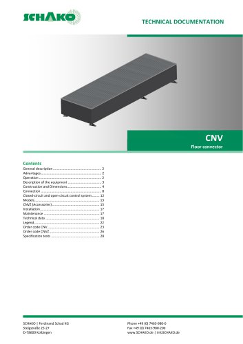
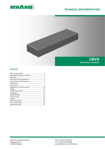
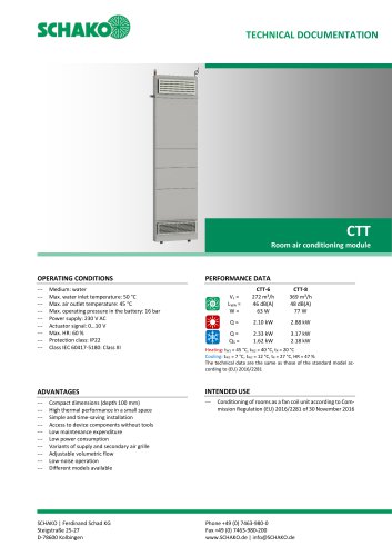
TECHNICAL DOCUMENTATION General description GENERAL DESCRIPTION SCHAKO's passive floor convectors CNV as decentralised airconditioners (heating mode) enable energy-efficient and comfortable air-conditioning of offices and administration buildings, exhibition and sales rooms, private living spaces, and conservatories. Passive floor convectors work by the principle of natural convection. Cold air close to the floor flows into the convector, is heated by the heat exchanger and flows upwards. The main area of use of floor convectors of this type is as addition to other heating systems and as an autonomous...
Open the catalog to page 2
CNV - Floor convector TECHNICAL DOCUMENTATION Description of the equipment MODELS 1 - Housing — Made of galvanised sheet steel, painted internally and externally to RAL 9005 (black), with pre-marked connection openings for hydraulic connections. Total length up to < 4000 mm Band design: — without end pieces (-E0) — with 1 end piece on the right (-ER) --- with 1 end piece on the left (-EL) Single convector with 2 end pieces (-E2) (standard) Housing outside: --- painted to RAL 9005 (black) (-A1) (standard) --- painted with polyester powder as rust protection (-A2) — With impact sound insulation...
Open the catalog to page 3
CNV - Floor convector TECHNICAL DOCUMENTATION Construction and Dimensions ATTENTION For all dimensions given, the dimensions of projecting fastening elements have not been taken into account. * Dry weight per metre with linear grille, frame, spacer bridges and water register, without connections. Table 1: Constructive features CNV Construction subject to change. Return not possible. Version: 2017-03-09 | Page 4
Open the catalog to page 4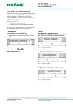
TECHNICAL DOCUMENTATION Construction and Dimensions TOTAL LENGTH AND REGISTER POSITION All passive floor convectors can be lengthened with inactive parts to a total length (-LG) of ≤4000 to adjust them to the structural conditions or to adjust them architecturally. Additional flexibility is achieved by having the option of selecting the register position. xxxx = Total length (LG) --- Nominal length up to < 4000 mm --- The total length (LG) must be entered with 4 digits. The position of the floor convector in the housing depends on the total length, the following options being possible: Total...
Open the catalog to page 5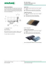
TECHNICAL DOCUMENTATION Construction and Dimensions Upper frame: The tread-resistant grille of the passive floor convectors CNV consists of a linear grille or a roll-down grille (optional) which, fitted in a frame and reinforced with several spacer bridges, serves for transmitting and distributing the load uniformly all the way to the adjusting legs. G1 = Extruded aluminium profiles natural colour anodised E6/EV1 G2 = Extruded aluminium profiles black anodised E6/EV6 G3 = Extruded aluminium profiles bronze anodised E6/C33 SCHAKO linear grille PA: L1 = Linear grille aluminium natural colour anodised...
Open the catalog to page 6
CNV - Floor convector TECHNICAL DOCUMENTATION Construction and Dimensions PRIMARY AIR CONNECTION SPIGOT In the complete CNV series, additional spigots with air diffuser plates for introducing conditioned fresh air can be used for covering all possible air-conditioning needs. Spigot diameter: PI = Width of rectangular spigot = as ordered, without GD Rubber lip seal (-GD) Rubber lip seal for the primary air connection spigot for airtight connection between device and duct. Table 2: Possible primary air connection spigots Primary air connection spigot position 1 = Primary air connection spigot in...
Open the catalog to page 7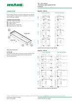
TECHNICAL DOCUMENTATION Connection CONNECTION POSITION W1 = Left end face (standard) W2 = Right end face W3 = Left front face - Room side W4 = Right front face - Room side The housings of the floor convectors CNV are pre-punched for various positions of the electrical and hydraulic connections, thus facilitating installation. Facade side Room side Figure 19: Connection position for type CNV 190 Figure 18: Connection side Model B = 270 mm Room side (-W3/-W4) ATTENTION The position of the water connections and the position of the primary air connection spigot without housing extension must not...
Open the catalog to page 8
CNV - Floor convector TECHNICAL DOCUMENTATION ConnectionModel B = 350 mm End face (-W1/-W2) Room side (-W3/-W4) Model B = 400 mm End face (-W1/-W2) Room side (-W3/-W4) Construction subject to change. Return not possible.
Open the catalog to page 9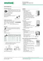
CNV - Floor convector TECHNICAL DOCUMENTATION Connection WATER CONNECTION Plug fitting male thread Actuators Rotating plug fitting with male thread K" flatsealing. Fitting body made of brass, sealing rings made of rubber and clamping ring made of stainless steel. Figure 23: Plug fitting male thread Eurocone connections Spigot nut female thread %" Eurocone for copper pipe 15. Model STA — Actuating power 100 N --- Simple installation --- Standard version prewired --- Motion and position indicator — Two-/ three-wire connection — Pulse width modulation (PDM) — STA23:Actuator thermal, operating voltage...
Open the catalog to page 10
CNV - Floor convector TECHNICAL DOCUMENTATION Connection WATER CONNECTION OPTIONS 6 = Straight-through valve, shut-off valve and actuator _continuous 24V (motorised), LGmin=NL+100 mm Construction subject to change. Return not possible. Version: 2017-03-09 | Page 11
Open the catalog to page 11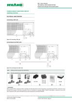
TECHNICAL DOCUMENTATION Closed-circuit and open-circuit control system CLOSED-CIRCUIT AND OPEN-CIRCUIT CONTROL SYSTEM ELECTRICAL JUNCTION BOX Connecting a CNV unit Figure 34: Connecting a CNV unit Connecting several CNV units Figure 35: Connecting several CNV units without electric junction box (standard) Electric junction box, with terminal strip, internally prewired * ATTENTION When using the floor convectors CNV in parallel, the load limits of the control and power consumption of the floor convectors must be taken into account. If the floor convectors CNV are controlled via actuators SSA61,...
Open the catalog to page 12
CNV - Floor convector TECHNICAL DOCUMENTATION Models END PIECE The CNVs can be installed individually or in band design with an end piece on both sides, only on the right or only on the left, or without an end piece.. EO = Band design, central part without end piece ATTENTION For perfect alignment of the units, the four connecting parts should be installed and fastened using the delivered screws. EXTERNAL COATING Housing painted externally to RAL9005 (-A1) (standard), or painted with polyester powder as rust protection (-A2). Optional: Impact-sound insulation made of 3-mm polyethylene on the...
Open the catalog to page 13All SCHAKO KG catalogs and technical brochures
 CNVA
CNVA32 Pages
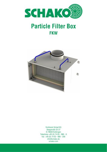 FKW (2025)
28 Pages
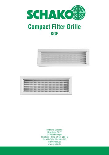 KGF Compact Filter Grille
9 Pages
 AUDIX
AUDIX2 Pages
 DISA
DISA4 Pages
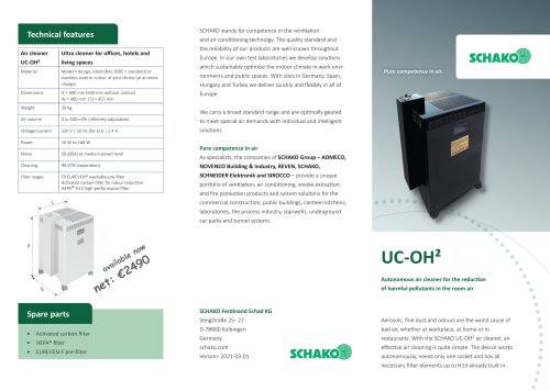 UC-OH²
2 Pages
 IGA
IGA2 Pages
 CDD
CDD2 Pages
 FBS
FBS18 Pages
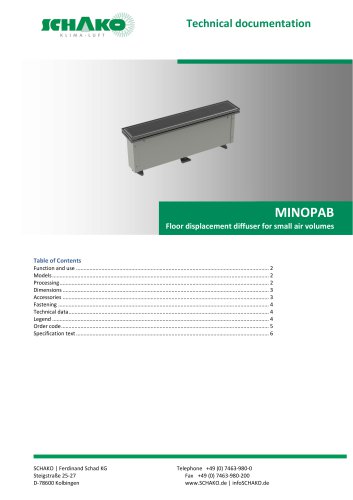 MINOPAB (2025)
6 Pages
 PIL
PIL23 Pages
 MWS / MWK
23 Pages
 ERK-SO
43 Pages
 DSCXL
DSCXL17 Pages
 DSCPL
DSCPL16 Pages
 BKSYS
BKSYS18 Pages
 MINODSA
6 Pages
 DKA
DKA6 Pages
 LAQ
LAQ11 Pages
 VMPR/VMPQ
29 Pages
 DSCU
DSCU18 Pages
 DSCP
DSCP15 Pages
 DQJP
DQJP9 Pages
 BKA-EN
79 Pages
 CPL
CPL15 Pages
 AUDIX®
25 Pages
 VREX
VREX26 Pages
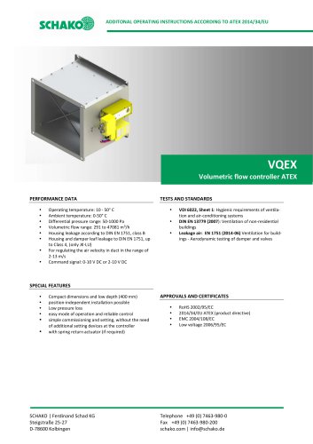 VQEX
VQEX17 Pages
 VPEX
VPEX18 Pages
 SVA-FS
11 Pages
 NRWG
NRWG22 Pages
 COMBIDSC
26 Pages
 DSC
DSC37 Pages
 DO
DO10 Pages
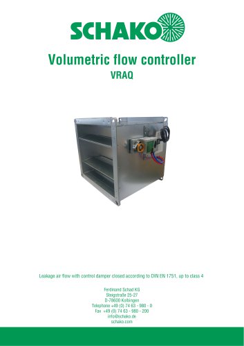 VRAQ
VRAQ46 Pages
 UEKU
UEKU6 Pages
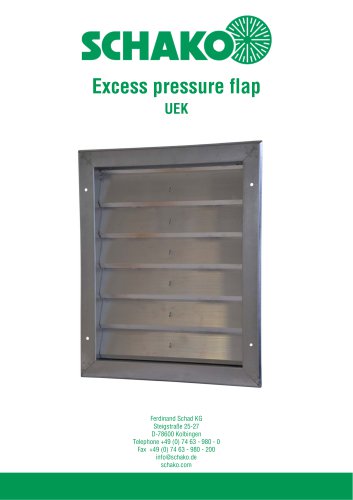 UEK
UEK6 Pages
 SS-K
SS-K6 Pages
 VOLKOM
6 Pages
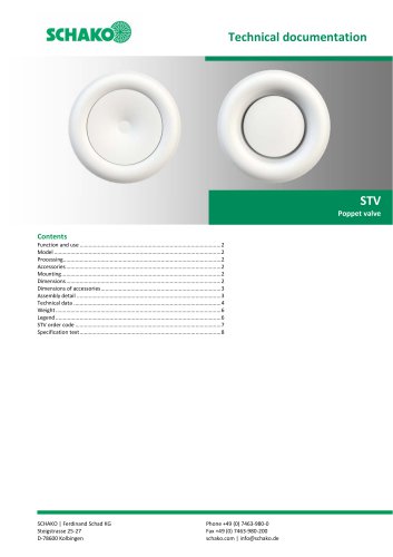 STV
STV8 Pages
 DQJ
DQJ38 Pages
 ALAS-F 125
6 Pages
 ALPETY
16 Pages
 CTT
CTT23 Pages
 KWB
KWB19 Pages
 GREENKIT
20 Pages
 SVA-FF
15 Pages
 FKU
FKU31 Pages
 FKF
FKF29 Pages
 SGA
SGA5 Pages
 DBB
DBB27 Pages
 TVO
TVO8 Pages
 AL
AL23 Pages
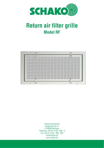
 RF Return air filter grille
7 Pages
 NBS
NBS34 Pages
 MKAR_MKAQ
13 Pages
 KF
KF4 Pages
 JK
JK16 Pages
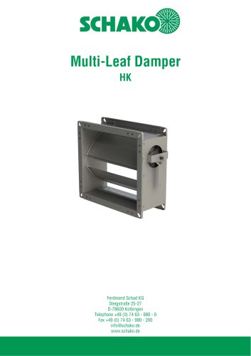 HK
HK16 Pages
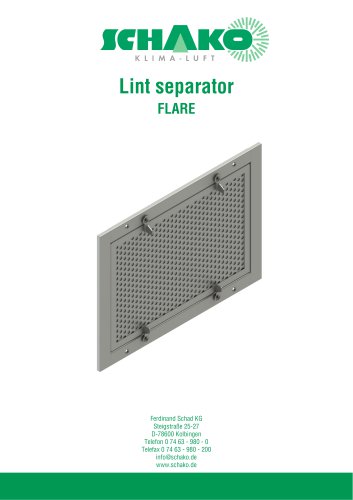
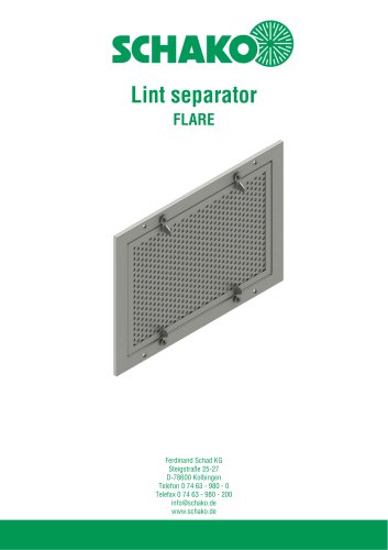 Lint Separator FLARE
13 Pages
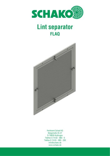 FLAQ
FLAQ11 Pages
 FG
FG14 Pages
 ERK-MB
38 Pages
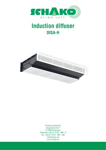
 DISA-H (2025)
34 Pages
 DISA-360
32 Pages
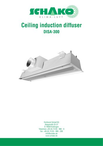 DISA-300
51 Pages
 BKP-EN Fire damper
40 Pages
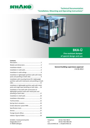 BKA-UE
35 Pages
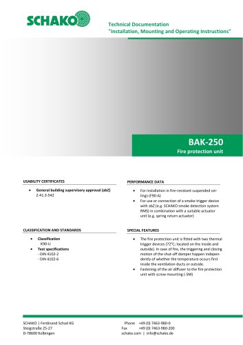 BAK-250 Fire protection unit
17 Pages
 BAK-240
16 Pages
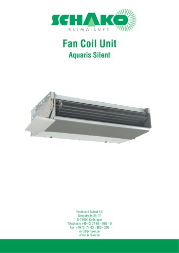
 Aquaris-Silent
38 Pages
 Aquaris_KWB
20 Pages
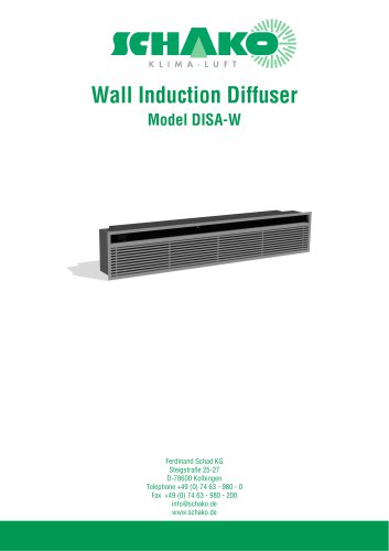 DISA-W
43 Pages
 CULTRA-Studioline
24 Pages
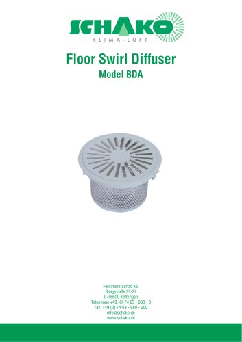 BDA
BDA11 Pages
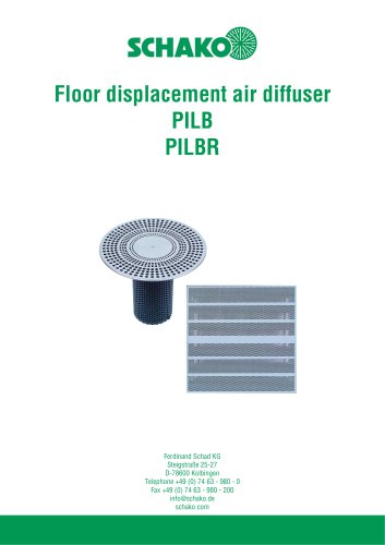 PILB/PILBR
33 Pages
 DAV
DAV19 Pages
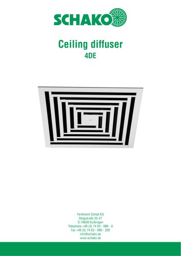 4DE
4DE18 Pages
 4DF
4DF13 Pages
 DQC
DQC16 Pages
 DQDL
DQDL16 Pages
 IDA
IDA21 Pages
 IKA
IKA23 Pages
 ZMD
ZMD17 Pages
 DQF
DQF15 Pages
 DQJF
DQJF12 Pages
 DQJA/DQJR
10 Pages
 DQJSL
DQJSL17 Pages
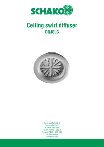 DQJSLC
17 Pages
 DHV
DHV18 Pages
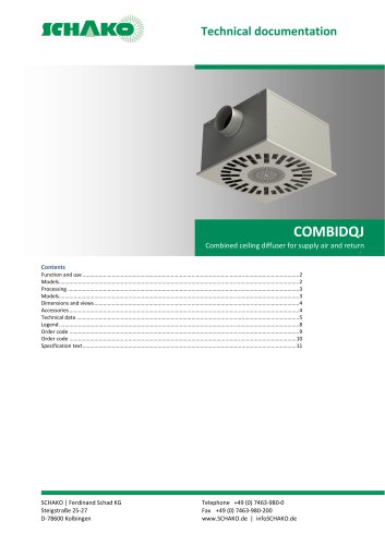 COMBIDQJ
11 Pages
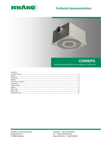 COMBIPIL
11 Pages
 DSA
DSA15 Pages
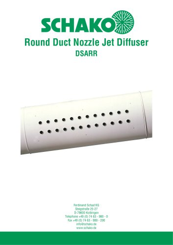 DSARR
DSARR7 Pages
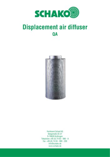 QA
QA30 Pages
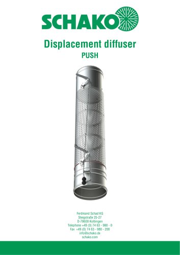 PUSH
PUSH23 Pages
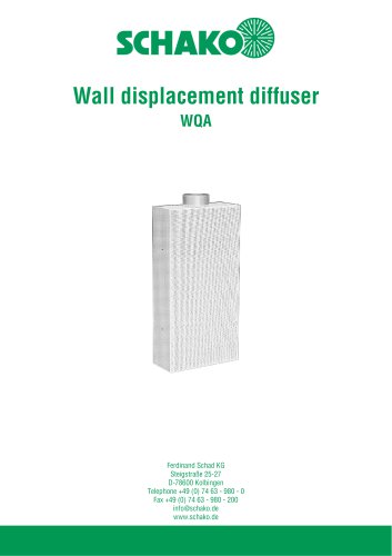 WQA
WQA12 Pages
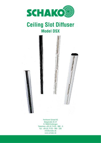 DSX
DSX25 Pages
 DSX-XXL
23 Pages
 AUDIX®-AW
20 Pages
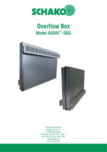 AUDIX®-ÜSG
13 Pages
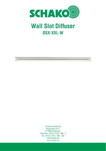 DSX-XXL-W
25 Pages
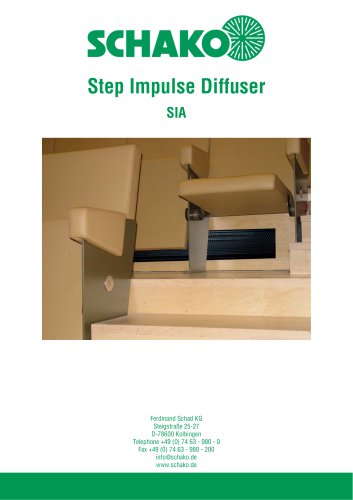 SIA
SIA7 Pages
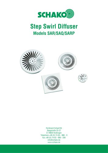 SAR/SAQ/SARP
13 Pages
 WDA
WDA32 Pages
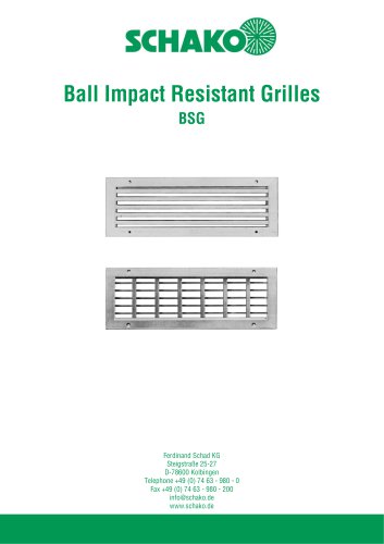 BSG
BSG19 Pages
 KG
KG19 Pages
 IB-Q
IB-Q21 Pages
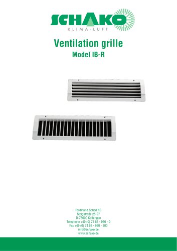 IB-R
IB-R15 Pages
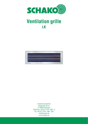 LK
LK12 Pages
 PA
PA32 Pages
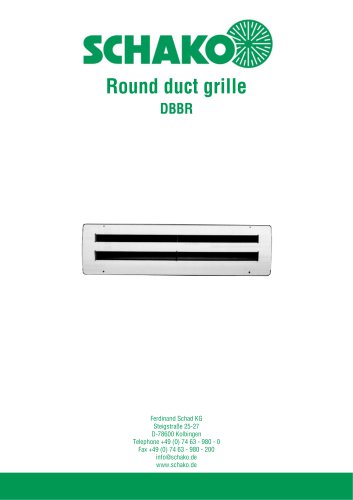 DBBR
DBBR6 Pages
 KGRR
KGRR17 Pages
 DBBRR
DBBRR11 Pages
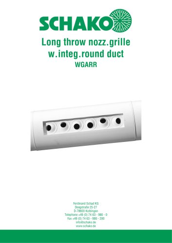 WGARR
WGARR7 Pages
 WGA
WGA29 Pages
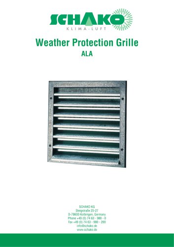 ALA
ALA4 Pages
 ALA-R
ALA-R4 Pages
 ALA-SO
4 Pages
 ALAS
ALAS10 Pages
 ALAS-P
5 Pages
 DKAPPs
6 Pages
 EBE/EBP
52 Pages
 DKG
DKG6 Pages
 MBE/MBP
27 Pages
 PIANO
PIANO27 Pages
 VAS
VAS26 Pages
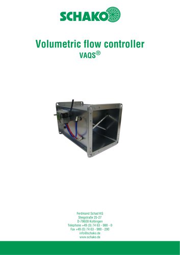 VAQS
VAQS19 Pages
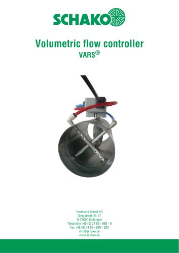 VARS
VARS26 Pages
 VRAPPs
20 Pages
 VRAR
VRAR52 Pages
 MAK
MAK15 Pages
 RS-F
RS-F7 Pages
 RS
RS15 Pages
 EasyBus
24 Pages
 DISA-Family
4 Pages
 RMS
RMS11 Pages
 TSR
TSR5 Pages
 VLV
VLV31 Pages
 MBM
MBM10 Pages
 LL
LL7 Pages
 RR-Complete
41 Pages
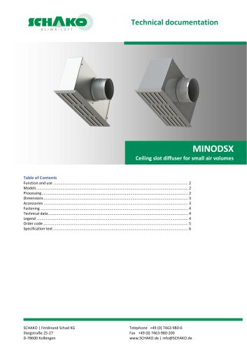 MINODSX
6 Pages
 SPB
SPB10 Pages
 DISA-H
34 Pages
 AQUARIS SILENT
38 Pages
 NBS
NBS24 Pages
 JK-LP/JK-LU
15 Pages
 HKP / HKU
16 Pages
 FKW
FKW16 Pages
 FLARE
FLARE13 Pages
 RF
RF7 Pages
 KGF
KGF9 Pages
 SVA-FF
8 Pages
 BKA-Ü
BKA-Ü35 Pages
 BSK-RPR
60 Pages
 BKP-EN
40 Pages
 BAK-240
6 Pages
 BAK-250
14 Pages


- Ventilation grill
- Industrial air conditioner
- Metal ventilation grill
- Rectangular ventilation grill
- Commercial detector
- Commercial air conditioning cabinet
- Reversible air conditioner
- Aluminum ventilation grill
- Exterior ventilation grill
- Commercial ventilation grill
- Facade ventilation grill
- Ceiling-mounted air diffuser
- Industrial fan coil
- White ventilation grill
- Home ventilation grill
- Metal convector
- Contemporary convector
- Wall-mounted air conditioner