


- Company
- Products
- Catalogs
- News & Trends
- Exhibitions
BSK-RPR

BSK-RPR
The BSK-RPR fire damper is certified for performance reliability under EU-Bau PVO 0761-CPR-0245 and holds an EC Certificate of Conformity 0761-CPD-0263. It also has a Declaration of Performance DoP-BSK-RPR-2017-08-09.
Classified under EN 13501-3 with a fire resistance rating of EI 90 (ve, ho i↔o) S, the fire damper complies with product standard EN 15650 and test standard EN 1366-2.
Designed for automatic locking of fire lobbies, it can connect to a smoke release device and integrate into building control systems via SCHAKO EasyBus or BKSYS fire damper mini-controller.
An ATEX version is available for explosion hazard areas. The housing is leakage class C according to EN 1751, and the damper can be equipped with various release devices, including spring return actuators and magnetic clamps.
The BSK-RPR fire damper is used in ventilation ducts to prevent fire and smoke spread. Constructed from galvanized sheet steel, with options for stainless steel or additional coatings, the damper leaf is made of silicate board. It can be installed in various positions regardless of airflow direction.
Available in nominal sizes from 100 to 500 mm, with options for plug-in or flanged connections. Detailed dimensions and installation configurations are provided for different mounting scenarios.
Comprehensive instructions are provided for installing the fire damper in solid walls, ceilings, and lightweight partition walls, with or without mounting frames. Specific configurations are outlined for different wall types and fire resistance requirements.
Includes specifications for limit switches, spring return actuators, and other accessories. The document also provides order codes and specification texts for procurement and installation purposes.
Emphasizes the importance of using appropriate cleaning materials for stainless steel versions and ensuring that building systems are arranged to prevent fire propagation.
Outlines installation and specifications for the Fire Damper Model BSK-RPR, including classifications according to EN 13501-2 or comparable national standards, with various configurations for mounting on lightweight partition walls and solid ceilings. Fire resistance classes range from EI 30 to EI 90, depending on the setup.
- General Installation: Fire dampers must be installed to avoid external forces impairing their function. PPE is required during installation to prevent injuries. Proper transport and storage conditions are necessary to avoid damage.
- Installation in Solid Walls: Involves filling circumferential gaps with mortar of category M15. The minimum gap size is 40 mm, and the distance between fire dampers should be at least 50 mm.
- Installation on Solid Walls with Mounting Frame AR: This dry installation requires a minimum distance of 200 mm between fire dampers and uses approved fastening materials.
- Installation Away from Solid Walls: Fire dampers must be suspended from the ceiling and connected to a fire-resistant ventilation duct.
- Installation in Solid Ceilings: Similar to wall installations, gaps must be filled with mortar, and the minimum distance between dampers is specified.
Emphasizes compliance with EN standards and the use of appropriate materials and methods to ensure fire resistance and structural integrity. Highlights the importance of following manufacturer guidelines for mortar and installation procedures.
- Ensure proper spacing and gap filling with mortar.
- Use mounting frame AR for specific installations.
- Follow safety protocols and use PPE during installation.
- Verify all electrical work is performed by qualified electricians.
Outlines installation on solid ceilings made of materials like concrete with a density of at least 500 kg/m³ and a minimum thickness of 125 mm. Requires a circumferential reinforced concrete base with specific dimensions and reinforcement details. The fire damper must be installed ensuring no interference with its function, and all fastening materials should be pre-installed. The distance between fire dampers should be at least 55 mm, and any gaps with adjacent components must be filled if they have F90 characteristics.
Fire dampers can be installed in lightweight partition walls with metal posts and gypsum-bonded wall boards. Flexible connection pieces are required, and all installation aids must be removed post-installation. Mortar lining is necessary for circumferential gaps, and specific distances from adjacent components must be maintained. The installation sequence involves mounting metal posts, inserting the fire damper, and filling gaps with mortar.
Describes dry installation using a mounting frame AR in lightweight partition walls. Requires flexible connection pieces and adherence to minimum distance requirements between dampers and adjacent components. The fire damper can be installed at any position within the wall, allowing for flexibility in previously panelled walls. The installation sequence includes mounting metal posts, inserting the fire damper with the mounting frame, and securing it with drywall screws.
For installations close to the ceiling, the process involves using a mounting frame AR and requires additional accessories. The installation must be done during wall assembly and maintain specified distances from adjacent components. Flexible connection pieces are necessary, and no additional suspensions are allowed.
Provides detailed instructions for installing the BSK-RPR fire damper in lightweight partition walls with metal posts and gypsum-bonded wall boards. The installation can be performed in various configurations, including dry and wet installations, and close to solid ceilings.
- The BSK-RPR can be installed with a mounting frame AR at any position, considering minimum distances in the partition wall.
- Installation is independent of existing metal post profiles, allowing for installation in fully paneled walls.
- Fire dampers must maintain a minimum distance of 170-200 mm from each other and at least 75-85 mm from load-carrying components.
- Dry Installation: Involves mounting metal posts, leaving a recess for the damper, and using mineral wool for insulation. The damper is fastened using drywall screws and U-washers.
- Wet Installation: Similar to dry installation but includes filling joints with wall jointing material and removing mounting aids after setting.
- Installation Close to Ceiling: Requires specific attention to ceiling connections and involves using mineral wool strips and jointing material.
- Installations must comply with EN 13501-2 or comparable national standards.
- Use flexible connection pieces or aluminum ventilation ducts on both sides.
- No additional permanent suspensions or attachments are allowed.
- Fire damper model BSK-RPR with mounting frame AR.
- Mineral wool (non-flammable, density ≥ 100 kg/m³, melting point ≥ 1000°C).
- Profiles UW 50/40/06 and CW 50/50/06 for wall thickness adjustments.
- Figures illustrate installation sequences and configurations for different wall types and damper sizes.
- Dry Installation: Involves mounting the BSK-RPR with a mounting frame AR into a pre-prepared recess in the wall. Mineral wool is used to fill gaps, and the damper is secured using drywall screws and U-washers.
- Wet Installation: Similar to dry installation but involves additional steps like joint filling with wall jointing material. This method is used for nominal sizes 100 to ≤ 250.
- Installation Close to Ceiling: The BSK-RPR can be installed directly under a solid ceiling, maintaining a minimum distance of 200 mm between dampers and 75 mm from load-carrying components.
- Nominal sizes range from 100 to 500 mm.
- Minimum distance between fire dampers is 200 mm.
- Minimum distance from load-carrying components is 75 mm.
- Use flexible connection pieces on both sides of the damper.
- Remove all installation and mounting aids after installation.
- Ensure all connections are secure and comply with the specified standards.
The BSK-RPR fire damper is installed with a mounting frame AR into a wall recess. Fastening is done using drywall screws and U-washers. For nominal sizes 100-160, all fixing lugs are used, while for sizes 180-500, only the outer bores are utilized. The installation must adhere to the wall manufacturer's specifications.
Fire dampers connect to ventilation systems via ducts on one or both sides. If connected on one side, non-flammable security grilles are required on the opposite side. Local regulations must be followed, and expansion joints should be made of flammable materials. Flexible spigots or aluminium ducts can be used, and ducts must be suspended separately.
Installation must ensure minimum distances for accessibility, especially when multiple dampers are installed. Inspection openings in ventilation ducts are necessary for maintenance. Distances vary based on installation situations and must ensure sufficient space between components.
Suspensions use threaded rods, with fire protection insulation required for lengths over 1500 mm. Dowels must meet fire protection standards, with specific dimensions and tensile load requirements.
Pressure loss and noise levels are specified for different nominal sizes, with application limits of 1000 Pa operating pressure and face velocity ≤ 10 m/s. Free cross-section and weight tables provide detailed measurements for various sizes.
Optional accessories include stainless steel models, thermal release via fusible links, limit switches, electric spring return actuators, and smoke detection systems. Various connection and extension pieces are available, with specifications for materials and coatings.
Electric spring return actuators B10/B11 feature thermoelectric release devices with specific trigger temperatures. They ensure safety positions through spring force and display damper positions via micro switches. Manual actuation is possible, and functional checks can be conducted on-site.
Provides detailed specifications for various actuator models used in fire dampers, including B10/B11 and S10/S11. Key parameters include rated voltage, power consumption, motor runtime, and protection class. The actuators operate at different voltages (24V AC/DC and 230V AC) and have specific power consumption rates during operation and idle states.
Instructions are provided for replacing internal duct temperature fuses and entire actuator units if damaged. Emphasizes the importance of correct electrical connections and mechanical unlocking to ensure safety functions.
Outlines compliance with IEC/EN standards for protection classes and ambient conditions. Specifies the use of halogen-free cables and the importance of maintaining specific ambient temperatures and humidity levels.
Details on magnetic clamps, pulse magnets, and flexible spigots are included. These components are crucial for the operation and safety of the fire dampers, with specific instructions on their installation and use.
Tables provide technical data for actuators, including power consumption, auxiliary switch specifications, and motor runtime. Includes dimensions for extension pieces and round duct assembly parts.
Safety functions are only guaranteed with proper connection and mechanical unlocking. Highlights the need for compliance with local regulations for equipotential bonding and mechanical stress prevention on fire dampers.
Provides technical specifications for the Fire Damper Model BSK-RPR, which complies with EN 15650, EN 13501-3, and EN 1366-2 standards. Includes details on the construction materials, such as galvanised sheet steel for the housing and mineral silicate boards for the damper leaf. The damper is designed to maintain cross-section integrity, heat insulation, and smoke leakage resistance, classified as EI 90 (ve, ho, i↔o) S.
Installation guidelines specify that the damper can be installed in solid walls, ceilings, and lightweight partition walls with metal posts and panelling. Outlines the use of mounting frames and the necessity of considering wall thickness during installation.
The fire damper has been tested according to EN 1366-2 and holds the EU-Bau PVO 0761-CPR-0245 certificate. It is also certified for use in explosion hazard areas under Directive 2014/34/EU with specific actuators and safety temperature limiters.
For optimal performance, recommends using specific actuators and accessories, such as electric spring return actuators with thermoelectric release devices and communication devices for bus systems. Advises on the use of limit switches for position indication.
Provides a detailed breakdown of the options available for the fire damper, including model type, nominal size, material, coating, damper leaf version, release temperature, actuator type, and accessories. Customers can select from various configurations to meet specific installation requirements.
Includes tables listing dimensions for duct connection spigots and order code options, providing essential data for selecting the appropriate components for installation.
Provides technical specifications and installation guidelines for the Fire Damper Model BSK-RPR. Includes detailed diagrams, tables, and figures to assist in the proper installation and understanding of the product.
Lists contact information for SCHAKO's foreign branch offices across various countries including Belgium, Denmark, England, France, Greece, Israel, Italy, Croatia, Luxembourg, Netherlands, Austria, Poland, Romania, Sweden, Switzerland, Serbia & Montenegro, Slovakia, Spain, Czech Republic, Turkey, and Hungary. Each entry includes addresses, phone numbers, fax numbers, and email addresses.
Contains a comprehensive list of figures, tables, and diagrams that detail the dimensions, installation methods, and technical specifications of the BSK-RPR model. Key figures include dimensions for different sizes, installation methods for various wall and ceiling types, and connection examples for ventilation systems.
- Dimensions for BSK-RPR-S and BSK-RPR-F models for various sizes.
- Installation methods for both wet and dry installations in massive walls and ceilings.
- Details on mounting and spacing requirements.
- Available sizes and flange drilling specifications.
- Technical data for different components like the B10/B11 and S10/S11 models.
- Weight and load capacity tables.
- Pressure loss and flow noise diagrams with and without end protection grilles.
- Diagrams illustrating the wiring and connection of various components.
- Emphasizes the importance of adhering to specified dimensions and installation methods to ensure the proper functioning of the fire damper.
- Highlights the need for correct spacing and mounting to maintain safety and efficiency.
- The technical data provided is crucial for selecting the appropriate model and understanding its capabilities and limitations.
Catalog excerpts

Technical documentation Installation, mounting and operating instructions BSK-RPR Fire damper Fig.: BSK-RPR with B10 drive USABILITY CERTIFICATES • • • Performance Reliability Certificate according to EU-Bau PVO 0761 – CPR – 0245 EC Certificate of Conformity 0761 – CPD – 0263 Declaration of Performance DoP-BSK-RPR-2017-08-09 PERFORMANCE DATA • • For automatic locking of fire lobbies For use or connection of a smoke release device with abZ (e.g. SCHAKO smoke detection system RMS) in connection with suitable release devices (e.g. spring return actuator) SPECIAL FEATURES CLASSIFICATION AND STANDARDS • • • Classification according to EN 13501-3, depending on the mounting situation EI 90 (ve, ho i↔o) S Product standard EN 15650 Test standard EN 1366-2 SCHAKO | Ferdinand Schad KG Steigstraße 25-27 D-78600 Kolbingen ATEX version available (at an extra charge) Extensive uses and applications Housing leakage class C according to EN 1751 For optimum integration into the building control system via the SCHAKO EasyBus signalling and switching bus system or the SCHAKO BKSYS fire damper mini-controller
Open the catalog to page 1
Fire Damper Model BSK-RPR Technical documentation Table of Contents Construction subject to change. No return possible
Open the catalog to page 2
Fire Damper Model BSK-RPR Technical documentation Description DESCRIPTION Fire dampers, installed in ventilation ducts (air conditioning systems), serve for the automatic locking of fire lobbies. The fire damper BSK-RPR corresponds to EN 15650, EN 135013 and EN 1366-2. The BSK-RPR has been tested according to EN 1366-2 in compliance with Declaration of Performance no. DoP-BSK-RPR-201708-09. It has the Performance Reliability Certificate according to EU-Bau PVO 0761-CPR-0245 and the EC Certificate of Conformity 0761-CPD-0263. Its category according to EN 13501-3 is EI 90 (ve, ho i ↔ o) S. According...
Open the catalog to page 3
Fire Damper Model BSK-RPR Technical documentation Models and dimensions MODELS AND DIMENSIONS BSK-RPR – Nominal sizes 100 to ≤ 250 BSK-RPR-S (plug-in connection) Fig. 1: Dimension BSK-RPR-S – Nominal sizes 100 to ≤ 250 BSK-RPR-S with mounting frame AR (Mounting frame AR only possible in -S design, pre-mounted ex works, delivery in loose form not possible) Fig. 2: Dimension BSK-RPR-S with mounting frame AR – Nominal sizes 100 to ≤ 250 BSK-RPR-F (flanged connection) Fig. 3: Dimension BSK-RPR-F – Nominal sizes 100 to ≤ 250 1 2 3 4 Housing Damper leaf Hand lever Locking profile Construction subject...
Open the catalog to page 4
Fire Damper Model BSK-RPR Technical documentation Models and dimensions BSK-RPR – Nominal sizes > 250 to 500 BSK-RPR-S (plug-in connection) Fig. 4: Dimension BSK-RPR-S – Nominal sizes >250 to 500 BSK-RPR-S with mounting frame AR (Mounting frame AR only possible in -S design, premounted ex works, delivery in loose form not possible) Fig. 5: Dimension BSK-RPR-S with AR – Nominal sizes > 250 to 500 BSK-RPR-F (flanged connection) Fig. 6: Dimension BSK-RPR-F – Nominal sizes > 250 to 500 1 2 3 4 Housing Damper leaf Hand lever Locking profile Construction subject to change. No return possible Trigger...
Open the catalog to page 5
Fire Damper Model BSK-RPR Technical documentation Models and dimensions Rubber lip seal for BSK-RPR-S Model BSK-RPR-S is delivered as standard with a rubber lip seal. Flange bores BSK-RPR-F SCHAKO ASG-RF / VT-RF / FS-RF: Flange bores suitable for BSK-RPR-F Fig. 8: Release device BSK-RPR Construction subject to change. No return possible
Open the catalog to page 6
Fire Damper Model BSK-RPR Technical documentation Models and dimensions Damper leaf projecting ends Nominal size * Extension piece (on site) necessary Table 3: Damper leaf projecting ends BSK-RPR-S "a"= 50 Minimum distance between the front edge mm: of the open damper leaf and the security grille (ASG) or flexible connection piece (FS). Nominal size * Extension piece (VT-RF) necessary Table 4: Damper leaf projecting ends BSK-RPR-F Construction subject to change. No return possible
Open the catalog to page 7
Fire Damper Model BSK-RPR Technical documentation Models and dimensions UseThe fire damper type BSK-RPR can be fitted as shown in the following table. Use 1) Installation only in connection with a ventilation duct devoid of openings (fire resistance duration 90 min.) between the BSK-RPR and the fire-resistant wall to be protected. Mounting only allowed in conjunction with mounting frame AR. 2) The exact wall thickness/es must be taken into account and specified when ordering. For installation, the accessories for sliding ceiling connection plus mounting frame AR are required. 3) At nominal sizes...
Open the catalog to page 8
Fire Damper Model BSK-RPR Technical documentation Installation details General information • During mounting or installation, there is a risk of injuries. To avoid any possible injuries, personal protective equipment (PPE) must be worn. • Fire dampers must be installed such that external forces do not impair their permanent functioning. During mounting it may be required to provide reinforcements for the housing or the like. The requirement of statically loadbearing lintels may have to be taken into consideration. • Improper transport/handling may result in damage/functional impairment. In addition...
Open the catalog to page 9
Fire Damper Model BSK-RPR Technical documentation Installation details Installation on solid walls with mounting frame AR Nominal sizes 100 to 500 - (dry installation) Installation on solid walls (shaft walls, shafts, ducts and fire walls) made of, for example, concrete, masonry according to EN 1996 or DIN 1053; solid plaster wall boards according to EN 12859 or DIN 18163; apparent density ≥ 450 kg/m³ and wall thickness W ≥ 100 mm only in conjunction with mounting frame AR. The distance of the fire dampers to one another must be at least 200 mm. (For nominal sizes 100 - 250, mounting is allowed...
Open the catalog to page 10
Fire Damper Model BSK-RPR Technical documentation Installation details Installation away from solid walls with mounting frame AR Nominal sizes 100 to 500 - (dry installation) Installation away from solid walls (shaft walls, shafts, ducts and fire walls) made of, for example, concrete, masonry according to EN 1996 or DIN 1053; solid plaster wall boards according to EN 12859 or DIN 18163; apparent density ≥ 450 kg/m³ and wall thickness W ≥ 100 mm only in conjunction with mounting frame AR. When fitting the fire damper away from solid walls, it must be suspended from the ceiling. Installation...
Open the catalog to page 11All SCHAKO KG catalogs and technical brochures
 CNVA
CNVA32 Pages
 FKW (2025)
28 Pages
 KGF Compact Filter Grille
9 Pages
 AUDIX
AUDIX2 Pages
 DISA
DISA4 Pages
 UC-OH²
2 Pages
 IGA
IGA2 Pages
 CDD
CDD2 Pages
 FBS
FBS18 Pages
 MINOPAB (2025)
6 Pages
 PIL
PIL23 Pages
 MWS / MWK
23 Pages
 ERK-SO
43 Pages
 DSCXL
DSCXL17 Pages
 DSCPL
DSCPL16 Pages
 BKSYS
BKSYS18 Pages
 MINODSA
6 Pages
 DKA
DKA6 Pages
 LAQ
LAQ11 Pages
 VMPR/VMPQ
29 Pages
 DSCU
DSCU18 Pages
 DSCP
DSCP15 Pages
 DQJP
DQJP9 Pages
 BKA-EN
79 Pages
 CPL
CPL15 Pages
 AUDIX®
25 Pages
 VREX
VREX26 Pages
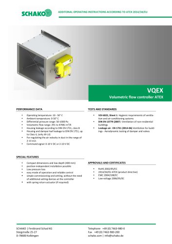 VQEX
VQEX17 Pages
 VPEX
VPEX18 Pages
 SVA-FS
11 Pages
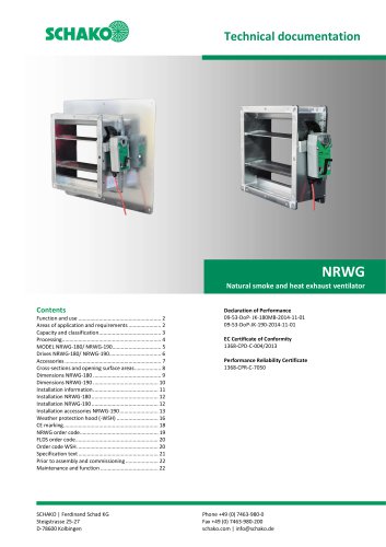 NRWG
NRWG22 Pages
 COMBIDSC
26 Pages
 DSC
DSC37 Pages
 DO
DO10 Pages
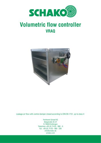 VRAQ
VRAQ46 Pages
 UEKU
UEKU6 Pages
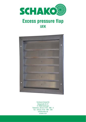 UEK
UEK6 Pages
 SS-K
SS-K6 Pages
 VOLKOM
6 Pages
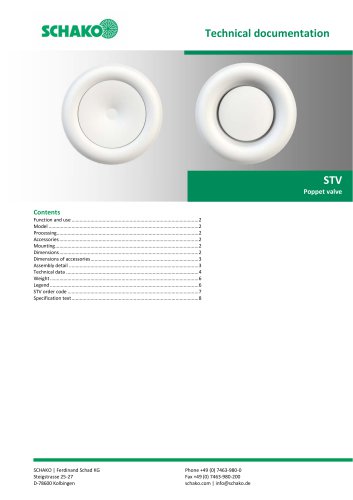 STV
STV8 Pages
 DQJ
DQJ38 Pages
 ALAS-F 125
6 Pages
 ALPETY
16 Pages
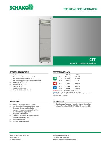 CTT
CTT23 Pages
 KWB
KWB19 Pages
 GREENKIT
20 Pages
 SVA-FF
15 Pages
 FKU
FKU31 Pages
 FKF
FKF29 Pages
 SGA
SGA5 Pages
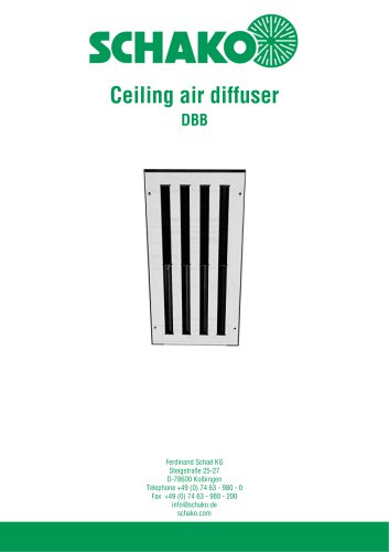 DBB
DBB27 Pages
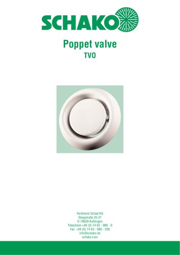 TVO
TVO8 Pages
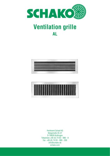 AL
AL23 Pages
 RF Return air filter grille
7 Pages
 NBS
NBS34 Pages
 MKAR_MKAQ
13 Pages
 KF
KF4 Pages
 JK
JK16 Pages
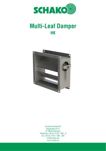 HK
HK16 Pages
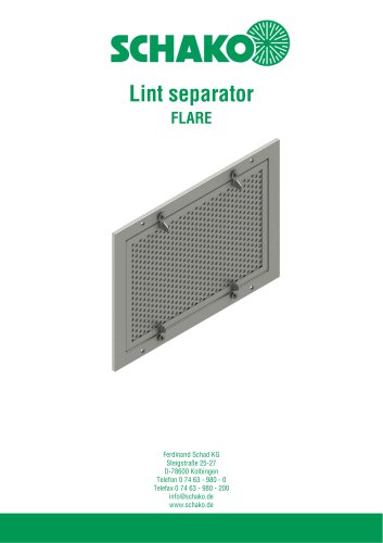 Lint Separator FLARE
13 Pages
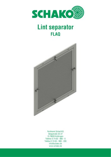 FLAQ
FLAQ11 Pages
 FG
FG14 Pages
 ERK-MB
38 Pages
 DISA-H (2025)
34 Pages
 DISA-360
32 Pages
 DISA-300
51 Pages
 CNV
CNV29 Pages
 BKP-EN Fire damper
40 Pages
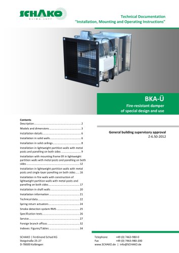 BKA-UE
35 Pages
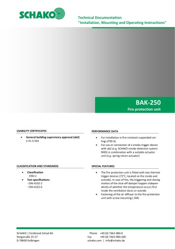 BAK-250 Fire protection unit
17 Pages
 BAK-240
16 Pages
 Aquaris-Silent
38 Pages
 Aquaris_KWB
20 Pages
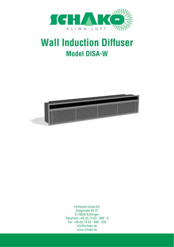 DISA-W
43 Pages
 CULTRA-Studioline
24 Pages
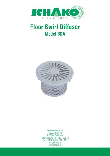 BDA
BDA11 Pages
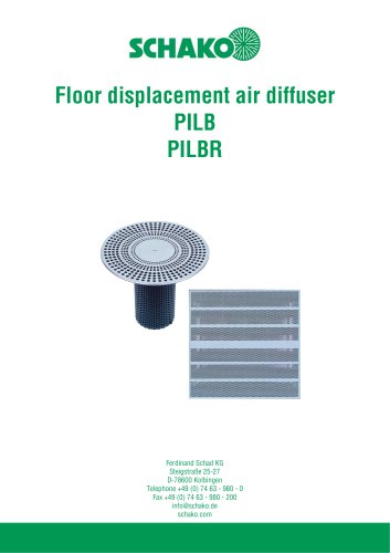 PILB/PILBR
33 Pages
 DAV
DAV19 Pages
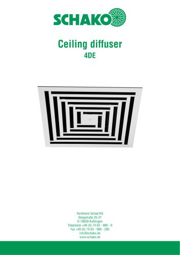 4DE
4DE18 Pages
 4DF
4DF13 Pages
 DQC
DQC16 Pages
 DQDL
DQDL16 Pages
 IDA
IDA21 Pages
 IKA
IKA23 Pages
 ZMD
ZMD17 Pages
 DQF
DQF15 Pages
 DQJF
DQJF12 Pages
 DQJA/DQJR
10 Pages
 DQJSL
DQJSL17 Pages
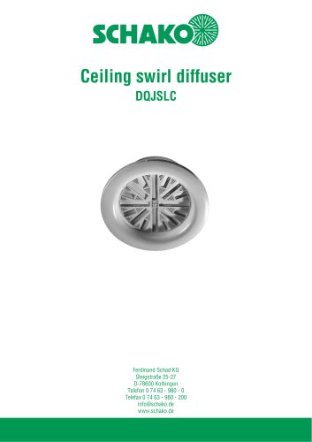 DQJSLC
17 Pages
 DHV
DHV18 Pages
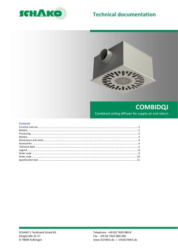 COMBIDQJ
11 Pages
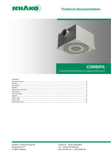 COMBIPIL
11 Pages
 DSA
DSA15 Pages
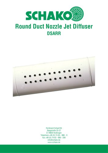 DSARR
DSARR7 Pages
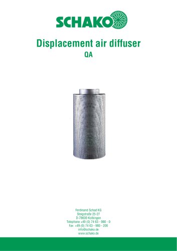 QA
QA30 Pages
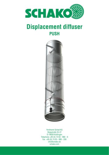 PUSH
PUSH23 Pages
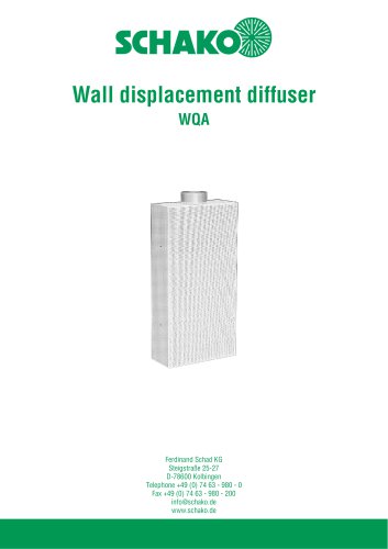 WQA
WQA12 Pages
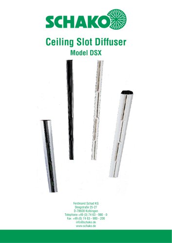 DSX
DSX25 Pages
 DSX-XXL
23 Pages
 AUDIX®-AW
20 Pages
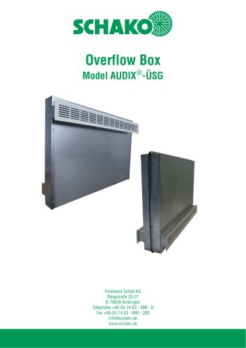 AUDIX®-ÜSG
13 Pages
 DSX-XXL-W
25 Pages
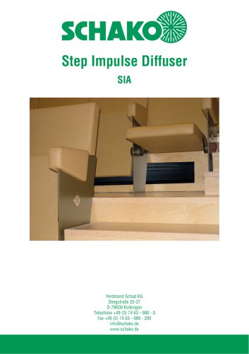 SIA
SIA7 Pages
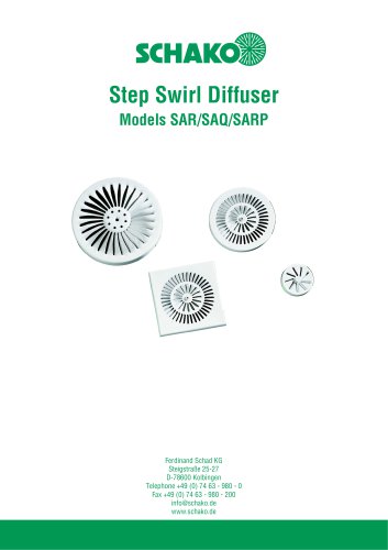 SAR/SAQ/SARP
13 Pages
 WDA
WDA32 Pages
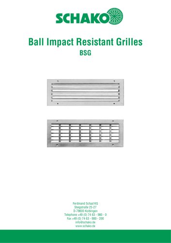 BSG
BSG19 Pages
 KG
KG19 Pages
 IB-Q
IB-Q21 Pages
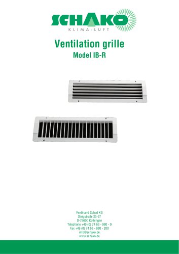 IB-R
IB-R15 Pages
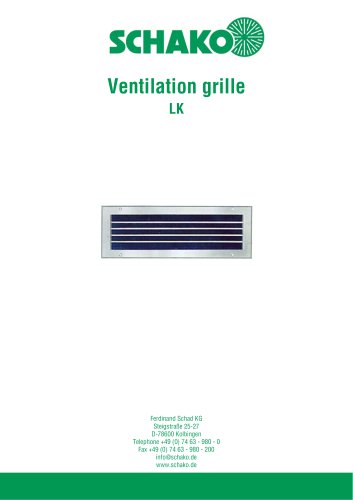 LK
LK12 Pages
 PA
PA32 Pages
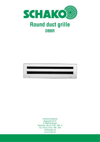 DBBR
DBBR6 Pages
 KGRR
KGRR17 Pages
 DBBRR
DBBRR11 Pages
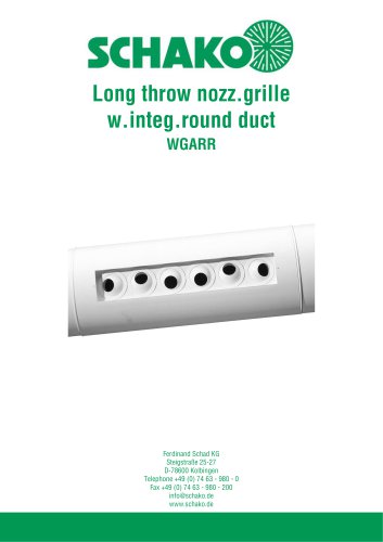 WGARR
WGARR7 Pages
 WGA
WGA29 Pages
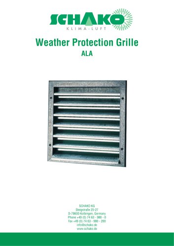 ALA
ALA4 Pages
 ALA-R
ALA-R4 Pages
 ALA-SO
4 Pages
 ALAS
ALAS10 Pages
 ALAS-P
5 Pages
 DKAPPs
6 Pages
 EBE/EBP
52 Pages
 DKG
DKG6 Pages
 MBE/MBP
27 Pages
 PIANO
PIANO27 Pages
 VAS
VAS26 Pages
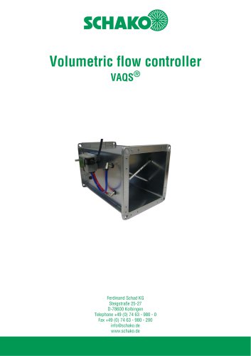 VAQS
VAQS19 Pages
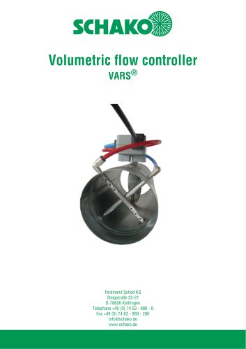 VARS
VARS26 Pages
 VRAPPs
20 Pages
 VRAR
VRAR52 Pages
 MAK
MAK15 Pages
 RS-F
RS-F7 Pages
 RS
RS15 Pages
 EasyBus
24 Pages
 DISA-Family
4 Pages
 RMS
RMS11 Pages
 TSR
TSR5 Pages
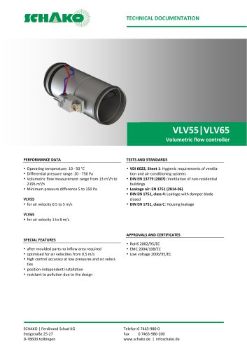 VLV
VLV31 Pages
 MBM
MBM10 Pages
 LL
LL7 Pages
 RR-Complete
41 Pages
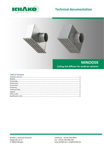 MINODSX
6 Pages
 SPB
SPB10 Pages
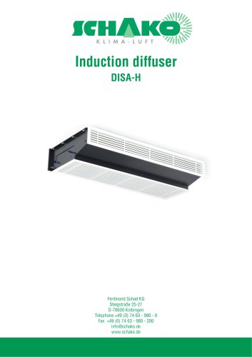 DISA-H
34 Pages
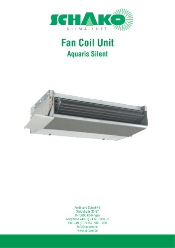 AQUARIS SILENT
38 Pages
 NBS
NBS24 Pages
 JK-LP/JK-LU
15 Pages
 HKP / HKU
16 Pages
 FKW
FKW16 Pages
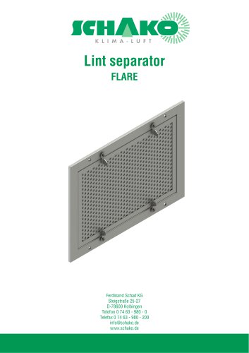 FLARE
FLARE13 Pages
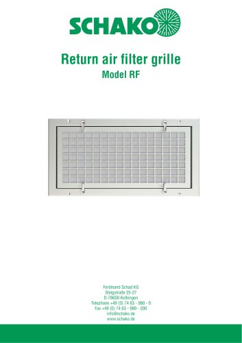 RF
RF7 Pages
 KGF
KGF9 Pages
 SVA-FF
8 Pages
 BKA-Ü
BKA-Ü35 Pages
 BKP-EN
40 Pages
 BAK-240
6 Pages
 BAK-250
14 Pages


- Ventilation grill
- Industrial air conditioner
- Metal ventilation grill
- Rectangular ventilation grill
- Commercial air conditioning cabinet
- Commercial detector
- Industrial air diffuser
- Reversible air conditioner
- Exterior ventilation grill
- Aluminum ventilation grill
- Facade ventilation grill
- Commercial ventilation grill
- Ceiling-mounted air diffuser
- Industrial fan coil
- White ventilation grill
- Industrial convector
- Metal convector
- Home ventilation grill
- Contemporary convector
- Wall-mounted air conditioner