- Company
- Products
- Catalogs
- News & Trends
- Exhibitions
BKSYS
1 /18Pages

BKSYS
1 /18Pages
Catalog excerpts

Technical documentation Technical documentation SCHAKO | Ferdinand Schad KG Steigstraße 25-27 D-78600 Kolbingen VRA-Q-E-Ex Volumetric flow controller ATEX
Open the catalog to page 1
Fire damper mini-controller BKSYS TECHNICAL DOCUMENTATION Safety-related notes | Areas of application SAFETY-RELATED NOTES The connection to the electric mains must be performed by a qualified electrician. The transformers used for power supply must meet the requirements according to DIN EN 61558 / VDE 570 part 2-6. A corresponding fuse protection must be available on the mains side. The BKSYS fire damper mini-controller by SCHAKO controls and regulates up to 16 motorised fire dampers (24V AC/DC) or up to 32 fire dampers with a limit switch. The basic module BKSYS-GM1 can be easily extended by...
Open the catalog to page 2
Fire damper mini-controller BKSYS TECHNICAL DOCUMENTATION System components | SYSTEM COMPONENTS EXPANSION MODULE BKSYS-EM1 BASIC MODULE BKSYS-GM1 The power supply of all connected expansion modules and spring return actuators is performed via the basic module BKSYS-GM1. Furthermore, the basic module BKSYS-GM1 controls and regulates the potential-free inputs and outputs, integrates the smoke detectors and forwards the data via the ring buffer and RS232/USB interface to the user. All functions in the basic module BKSYS-GM1 have been designed for maximum simplicity and maximum safety at the same...
Open the catalog to page 3
Fire damper mini-controller BKSYS TECHNICAL DOCUMENTATION | Configuration CONNECTION SOCKET BKSYS-ADM CONFIGURATION PARAMETERISATION The following configuration parameters can be set using the PC converter BKSYS-USB and the associated PC program. --- Date/Time is taken from the system time of the PC (no automatic switching from daylight saving time to standard time) --- potential-free fault input (smoke detector) --- for the connection of the spring return actuator 24V AC/DC --- with connection for the plugs (power supply and limit switch) of the spring return actuator 24V AC/DC --- spring-type...
Open the catalog to page 4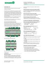
Fire damper mini-controller BKSYS TECHNICAL DOCUMENTATION | Configuration FUNCTIONAL TEST The test run serves for functional check of the connected spring return actuators. One button each on the BKSYS basic and expansion modules is used to start the functional test. The spring return actuators assigned to the corresponding basic or expansion module close the fire dampers. After reaching the Closed position, the spring return actuators open the fire dampers again. During this functional test, the LEDs assigned to the spring return actuators are flashing. The same functional test can also be performed...
Open the catalog to page 5
Fire damper mini-controller BKSYS TECHNICAL DOCUMENTATION Technical data | Assembly TECHNICAL DATA PERFORMANCE DATA Rated voltage: 24 V AC/DC +- 15% Current consumption: max. 3600 mA Power consumption per module: 5 VA Ambient temperature: 0°….. +55°C Storage temperature: (-) 20° to (+) 60°C Humidity: max. 80% relative, non-condensing The basic module BKSYS-GM1 and expansion modules BKSYSEM1 are mounted on the existing DIN rails and connected to each other using Plug and Play plug-in connection. The power supply for the expansion modules BKSYS-EM1 is performed via the basic module BKSYS-GM1. Switching...
Open the catalog to page 6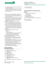
Fire damper mini-controller BKSYS TECHNICAL DOCUMENTATION | Commissioning sion modules BKSYS-EM1 (terminal X2 to BKSYS-GM1 and terminal X1 to BKSYS-EM1). If a smoke detector triggers an alarm, then this command is limited only to the connected module. Thus, only the motorised fire dampers connected to the corresponding module will be closed. TERMINAL ASSIGNMENT OF EXPANSION MODULE BKSYS-EM1 08. Select the setting in the ALARM DELAY checkbox: The set time indicates how long the fault output is disabled for maintenance purposes. Once the time has elapsed, the set value is reset to 0 minutes. 09....
Open the catalog to page 7
Fire damper mini-controller BKSYS TECHNICAL DOCUMENTATION Connection diagrams | CONNECTION DIAGRAMS CONNECTION OF BASIC MODULE BKSYS-GM1 CONNECTION 24 V AC/DC feed Smoke detector (RM) input Connection socket BKSYS-ADM for spring return actuators Mechanical fire damper with 2 limit switches (zero-current CLOSED) Voltage output 24 V AC/DC PC interface USB-RS232 Voltage output 24 V AC/DC Fan input Fault output (changeover contact) One mechanical fire damper with one limit switch Two mechanical fire dampers with one limit switch MOTOR CONNECTION SOCKET BKSYS-ADM Construction subject to change No...
Open the catalog to page 8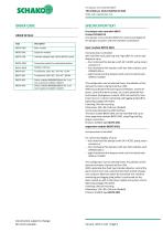
Fire damper mini-controller BKSYS TECHNICAL DOCUMENTATION Order code | Specification text ORDER CODE SPECIFICATION TEXT ORDER DETAILS Fire damper mini-controller BKSYS Product SCHAKO KG Fire damper mini-controller BKSYS for control and display of fire damper actuators and limit switches consisting of: Basic module Expansion module Interface adapter from USB to RS232 (serial) Connection socket for motorised actuators Modbus interface microprocessor-controlled with real-time clock, gold cap and ring buffer for control and display of up to: --- four motorised fire dampers with 24 V AC/DC spring...
Open the catalog to page 9
Fire damper mini-controller BKSYS TECHNICAL DOCUMENTATION Order code | Specification text Connection socket BKSYS-ADM according to degree of protection IP 66 Housing: Stable sheet steel construction consisting of 1.25 mm or 1.5 mm sheet steel, canted and welded from a single piece, with circumferential protective channel at the door opening, rear wall with countersunk bores for wall mounting support. Housing bottom with sheet steel flange plates. All modules are completely preassembled and prewired on terminal blocks. Maximum size: 2x GM1 + 6xEM1 Dimensions (W x H x D): 800 x 600 x 300 mm Product:...
Open the catalog to page 10
Fire damper mini-controller BKSYS TECHNICAL DOCUMENTATION Appendix Part 1 Modbus Interface | APPENDIX PART 1 MODBUS INTERFACE A transmitted message always contains all status information of exactly one module and the current system time. MODBUS CONFIGURATION The Modbus configuration must be set before initialisation and cannot be changed during operation. CONNECTIONS AND CONFIGURATIONS Switch for setting the unique address (hexadecimal) SETTING THE MODBUS ADDRESS Each Modbus slave requires a unique address in the allowed address space of 1 - 247 (decimal). The address 0 is reserved for broadcast...
Open the catalog to page 11All SCHAKO KG catalogs and technical brochures
 CNVA
CNVA32 Pages
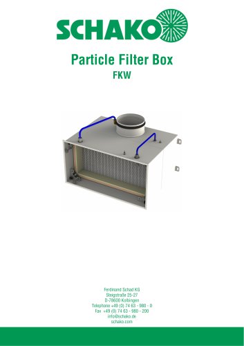 FKW (2025)
28 Pages
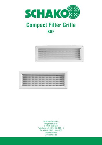 KGF Compact Filter Grille
9 Pages
 AUDIX
AUDIX2 Pages
 DISA
DISA4 Pages
 UC-OH²
2 Pages
 IGA
IGA2 Pages
 CDD
CDD2 Pages
 FBS
FBS18 Pages
 MINOPAB (2025)
6 Pages
 PIL
PIL23 Pages
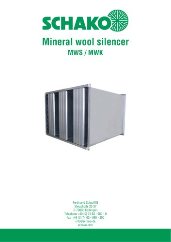 MWS / MWK
23 Pages
 ERK-SO
43 Pages
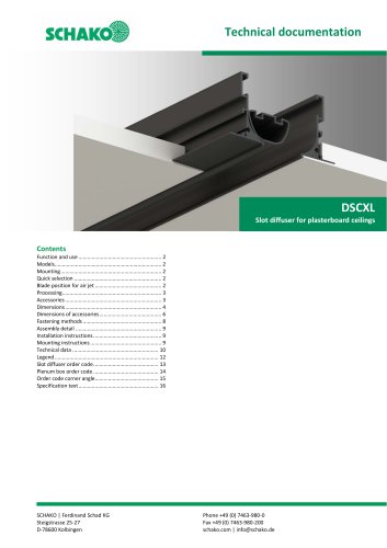 DSCXL
DSCXL17 Pages
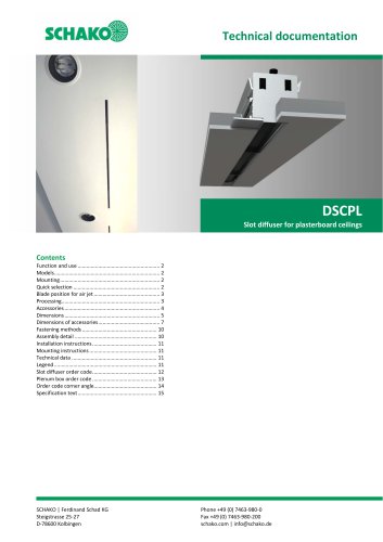 DSCPL
DSCPL16 Pages
 MINODSA
6 Pages
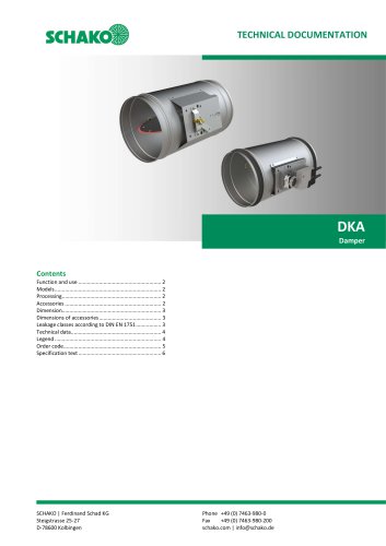 DKA
DKA6 Pages
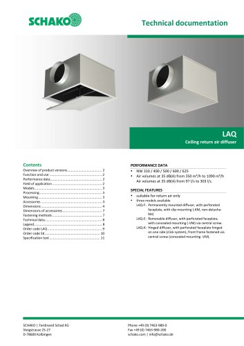 LAQ
LAQ11 Pages
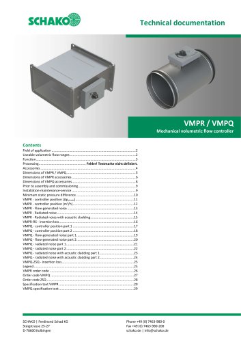 VMPR/VMPQ
29 Pages
 DSCU
DSCU18 Pages
 DSCP
DSCP15 Pages
 DQJP
DQJP9 Pages
 BKA-EN
79 Pages
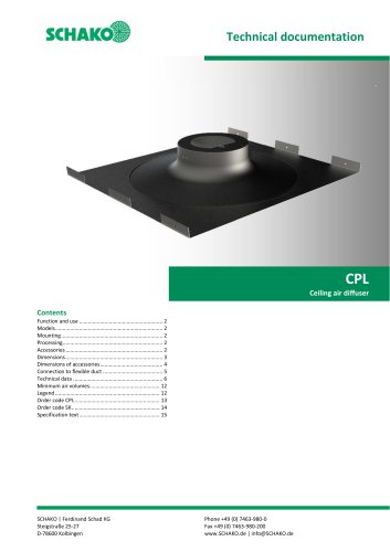 CPL
CPL15 Pages
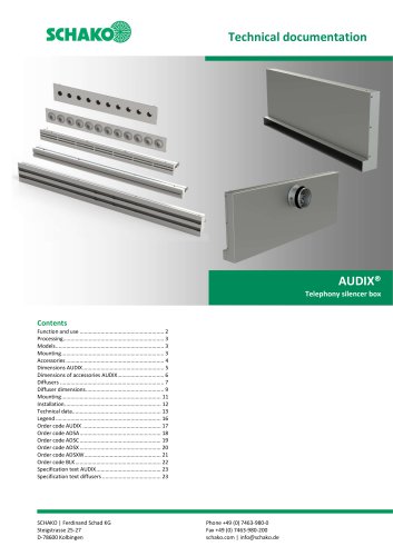 AUDIX®
25 Pages
 VREX
VREX26 Pages
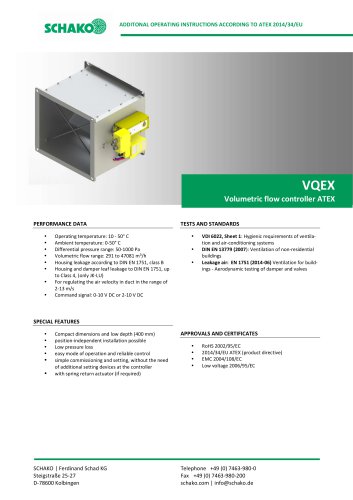 VQEX
VQEX17 Pages
 VPEX
VPEX18 Pages
 SVA-FS
11 Pages
 NRWG
NRWG22 Pages
 COMBIDSC
26 Pages
 DSC
DSC37 Pages
 DO
DO10 Pages
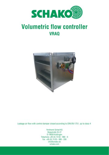 VRAQ
VRAQ46 Pages
 UEKU
UEKU6 Pages
 UEK
UEK6 Pages
 SS-K
SS-K6 Pages
 VOLKOM
6 Pages
 STV
STV8 Pages
 DQJ
DQJ38 Pages
 ALAS-F 125
6 Pages
 ALPETY
16 Pages
 CTT
CTT23 Pages
 KWB
KWB19 Pages
 GREENKIT
20 Pages
 SVA-FF
15 Pages
 FKU
FKU31 Pages
 FKF
FKF29 Pages
 SGA
SGA5 Pages
 DBB
DBB27 Pages
 TVO
TVO8 Pages
 AL
AL23 Pages
 RF Return air filter grille
7 Pages
 NBS
NBS34 Pages
 MKAR_MKAQ
13 Pages
 KF
KF4 Pages
 JK
JK16 Pages
 HK
HK16 Pages
 Lint Separator FLARE
13 Pages
 FLAQ
FLAQ11 Pages
 FG
FG14 Pages
 ERK-MB
38 Pages
 DISA-H (2025)
34 Pages
 DISA-360
32 Pages
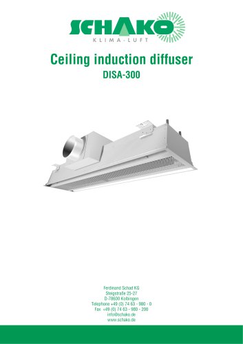 DISA-300
51 Pages
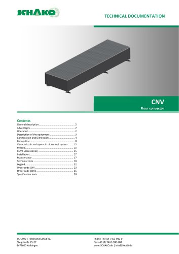 CNV
CNV29 Pages
 BKP-EN Fire damper
40 Pages
 BKA-UE
35 Pages
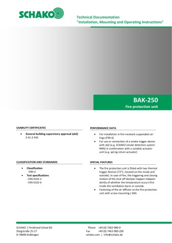 BAK-250 Fire protection unit
17 Pages
 BAK-240
16 Pages
 Aquaris-Silent
38 Pages
 Aquaris_KWB
20 Pages
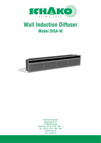 DISA-W
43 Pages
 CULTRA-Studioline
24 Pages
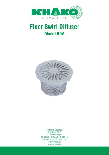 BDA
BDA11 Pages
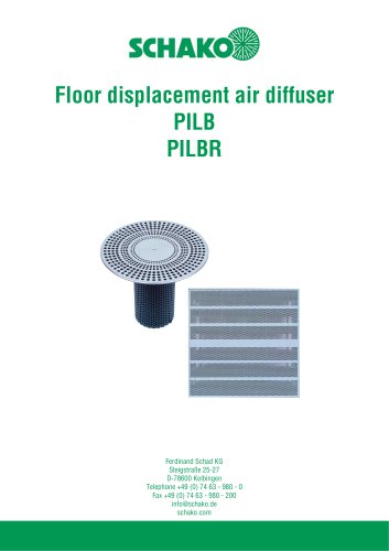 PILB/PILBR
33 Pages
 DAV
DAV19 Pages
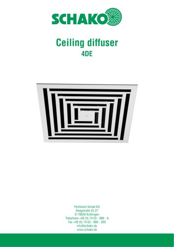 4DE
4DE18 Pages
 4DF
4DF13 Pages
 DQC
DQC16 Pages
 DQDL
DQDL16 Pages
 IDA
IDA21 Pages
 IKA
IKA23 Pages
 ZMD
ZMD17 Pages
 DQF
DQF15 Pages
 DQJF
DQJF12 Pages
 DQJA/DQJR
10 Pages
 DQJSL
DQJSL17 Pages
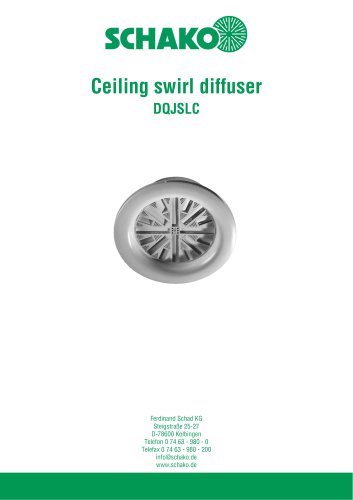 DQJSLC
17 Pages
 DHV
DHV18 Pages
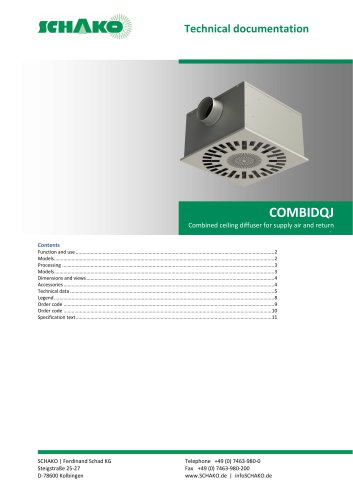 COMBIDQJ
11 Pages
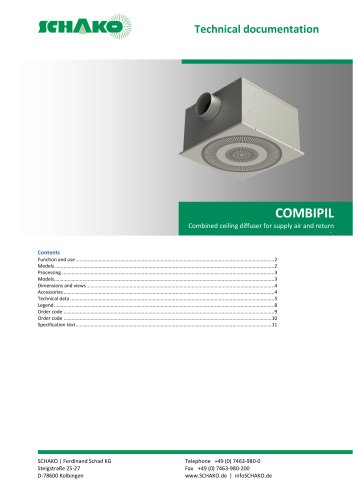 COMBIPIL
11 Pages
 DSA
DSA15 Pages
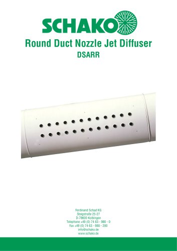 DSARR
DSARR7 Pages
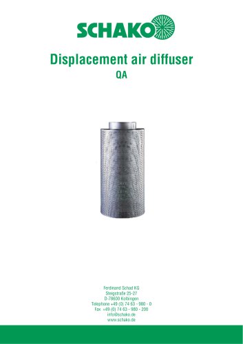 QA
QA30 Pages
 PUSH
PUSH23 Pages
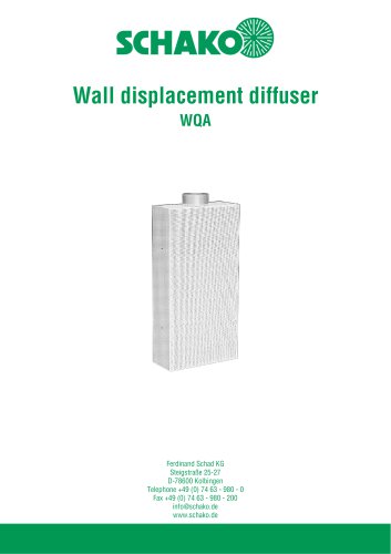 WQA
WQA12 Pages
 DSX
DSX25 Pages
 DSX-XXL
23 Pages
 AUDIX®-AW
20 Pages
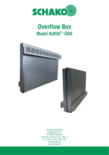 AUDIX®-ÜSG
13 Pages
 DSX-XXL-W
25 Pages
 SIA
SIA7 Pages
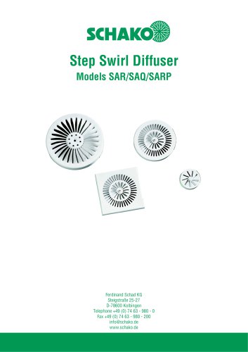 SAR/SAQ/SARP
13 Pages
 WDA
WDA32 Pages
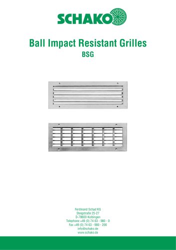 BSG
BSG19 Pages
 KG
KG19 Pages
 IB-Q
IB-Q21 Pages
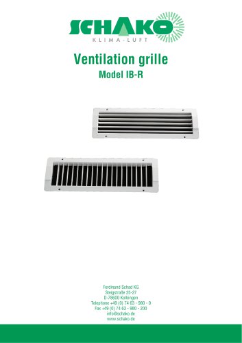 IB-R
IB-R15 Pages
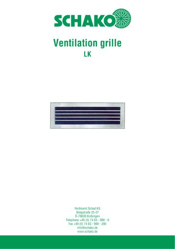 LK
LK12 Pages
 PA
PA32 Pages
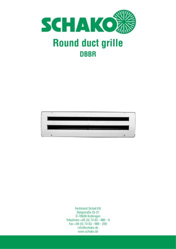 DBBR
DBBR6 Pages
 KGRR
KGRR17 Pages
 DBBRR
DBBRR11 Pages
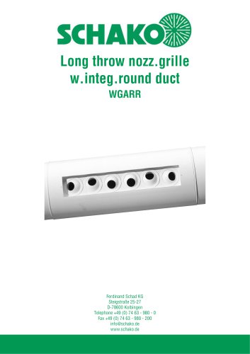 WGARR
WGARR7 Pages
 WGA
WGA29 Pages
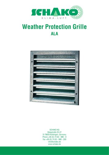 ALA
ALA4 Pages
 ALA-R
ALA-R4 Pages
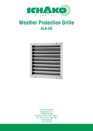 ALA-SO
4 Pages
 ALAS
ALAS10 Pages
 ALAS-P
5 Pages
 DKAPPs
6 Pages
 EBE/EBP
52 Pages
 DKG
DKG6 Pages
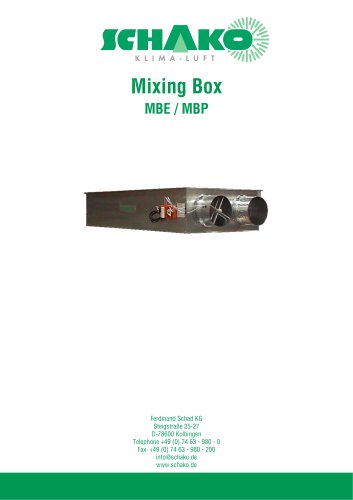 MBE/MBP
27 Pages
 PIANO
PIANO27 Pages
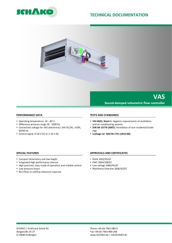 VAS
VAS26 Pages
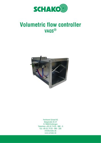 VAQS
VAQS19 Pages
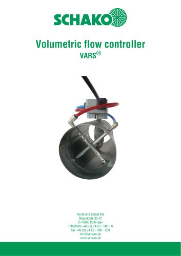 VARS
VARS26 Pages
 VRAPPs
20 Pages
 VRAR
VRAR52 Pages
 MAK
MAK15 Pages
 RS-F
RS-F7 Pages
 RS
RS15 Pages
 EasyBus
24 Pages
 DISA-Family
4 Pages
 RMS
RMS11 Pages
 TSR
TSR5 Pages
 VLV
VLV31 Pages
 MBM
MBM10 Pages
 LL
LL7 Pages
 RR-Complete
41 Pages
 MINODSX
6 Pages
 SPB
SPB10 Pages
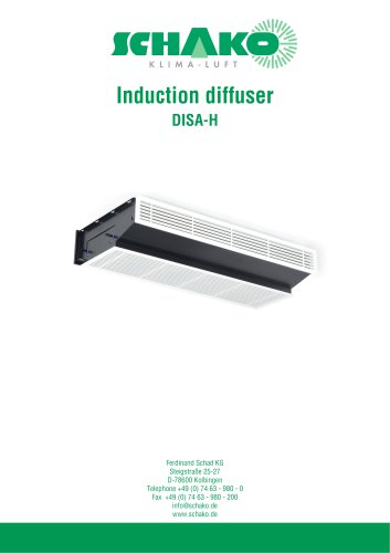 DISA-H
34 Pages
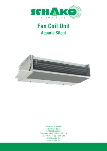 AQUARIS SILENT
38 Pages
 NBS
NBS24 Pages
 JK-LP/JK-LU
15 Pages
 HKP / HKU
16 Pages
 FKW
FKW16 Pages
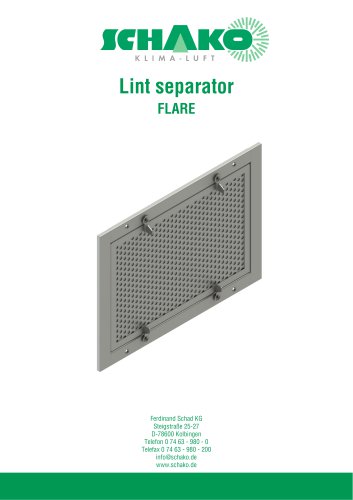 FLARE
FLARE13 Pages
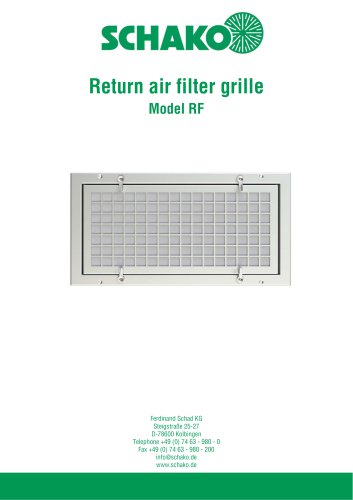 RF
RF7 Pages
 KGF
KGF9 Pages
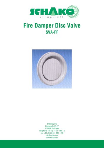 SVA-FF
8 Pages
 BKA-Ü
BKA-Ü35 Pages
 BSK-RPR
60 Pages
 BKP-EN
40 Pages
 BAK-240
6 Pages
 BAK-250
14 Pages


- Ventilation grill
- Industrial air conditioner
- Metal ventilation grill
- Rectangular ventilation grill
- Commercial detector
- Commercial air conditioning cabinet
- Industrial air diffuser
- Reversible air conditioner
- Aluminum ventilation grill
- Exterior ventilation grill
- Commercial ventilation grill
- Facade ventilation grill
- Ceiling-mounted air diffuser
- Industrial fan coil
- White ventilation grill
- Industrial convector
- Home ventilation grill
- Metal convector
- Contemporary convector
- Wall-mounted air conditioner