- Company
- Products
- Catalogs
- News & Trends
- Exhibitions
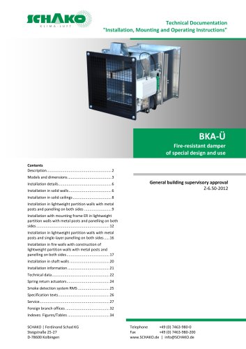
BKA-Ü

BKA-Ü
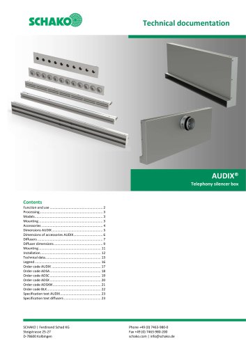
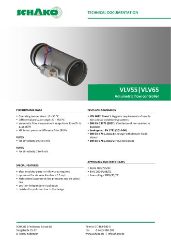
The document provides comprehensive technical specifications and installation guidelines for the fire-resistant damper model BKA-Ü, designed to prevent the spread of fire and smoke in ventilation systems. It includes detailed figures and tables to assist in understanding product dimensions, installation procedures, and technical data.
The BKA-Ü model includes components such as the SCHAKO shut-off damper, protective grating, and smoke detection system. Available sizes range from 200mm to 1500mm in width and height. The damper must comply with EN 13501-2 standards or equivalent national standards. The mineral wool used is non-flammable, with a packing density of 100 kg/m³ and a melting point of ≥ 1000°C.
Installation can be performed in solid walls, ceilings, and lightweight partition walls. Specific guidelines include ensuring the damper is not impaired by external forces, maintaining proper gap sizes filled with appropriate mortar, and ensuring smoke detectors are correctly positioned. Installation must adhere to the technical documentation and building approvals.
Various installation methods are illustrated, including wet and dry installations in different wall types. For solid walls, the wall must have an apparent density of at least 450 kg/m³ and a thickness of at least 100 mm. For solid ceilings, the ceiling must have an apparent density of at least 500 kg/m³ and a thickness of at least 125 mm. Lightweight partition walls require a minimum thickness of 100 mm. Figures 2 to 26 depict installation scenarios such as 'flange-to-flange' setups, mortar lining requirements, and mounting frame configurations.
The document provides tables detailing the free cross-section and weight of the damper based on various dimensions. It also includes technical data for spring return actuators, specifying power consumption, running time, and protection classes. A circuit diagram for the Relay module RM (V4.00) and actuator type assignments are provided in Tables 6 and 7.
Fire-resistant dampers require regular maintenance, including cleaning with suitable materials and ensuring all components are functioning correctly. Inspection openings should be provided for easy access.
Optional features include stainless steel models and additional coatings for enhanced durability. The document also outlines the use of spring return actuators and smoke detection systems for automatic operation during a fire.
Ensure adherence to minimum gap sizes and proper installation techniques as depicted in the figures to maintain fire resistance integrity. Follow the specified technical data for optimal performance. Remove all temporary mounting aids after installation and ensure all connections are riveted, crimped, or screwed for stability.
Catalog excerpts

Technical Documentation "Installation, Mounting and Operating Instructions" General building supervisory approval Z-6.50-2012
Open the catalog to page 1
Fire-resistant damper model BKA-Ü Technical documentation Description DESCRIPTION Fire-resistant dampers of special design and use are used if, as part of ventilation planning, openings are required in fireresistant inner walls or ceilings for the air intake, they must be closed in the event of a fire. The competent building supervisory authority will decide whether the opening is admissible, for example because it differs or in connection with the approval of the fire protection concept. The required dampers are fire-resistant dampers which are closed in case of fire driven by a suitable smoke...
Open the catalog to page 2
ichAkoIFire-resistant damper model BKA-U Technical documentation Models and dimensionsMODELS AND DIMENSIONSDimensions Legend Width Height Length Density at least maximum or approximately Utility company Version: 2015-08-17 | Document: 09/20 | Page 3 Construction subject to change No return possible 1 Fire damper BKA-EN (component of BKA-U) Assembly part type EBT Extension piece type VT Finishing protective grating type ASG Electric spring return actuator 24 V Smoke detector RMSII-L Protective cover
Open the catalog to page 3
vchAko Fire-resistant damper model BKA-U Technical documentation Models and dimensions Table 1: Available sizes Available at an extra charge • All heights and widths which can be combined are available! • Drive unit always on the H side of the fire damper. • Inspection openings always on the B side of the fire damper. • On request, the width and height dimensions are available in steps of 10 mm. • For wall installation, the smoke detector must always be installed above in the assembly part type EBT with the damper blade axle in the horizontal position. • Stainless steel model with material no....
Open the catalog to page 4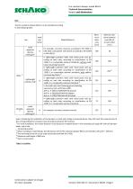
ichAkoIFire-resistant damper model BKA-U Technical documentation Models and dimensionsUse The fire-resistant damper BKA-U can be installed according to the following table. Even considering the installation of the dampers in walls and ceilings mentioned above, they still meet the requirements of the corresponding fire resistance class (resistance duration 90 minutes). 11 For wall installation, the smoke detector must always be installed above in the assembly part type EBT with the damper blade axle in the horizontal position. 2) When installing in solid ceilings, the dimensions of the fire-resistant...
Open the catalog to page 5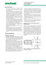
Fire-resistant damper model BKA-Ü Technical documentation Installation details Risk of injuries during mounting or installation. To avoid any possible injuries, personal protective equipment (PPE) must be worn. Fire-resistant dampers must be installed such that external forces do not impair their continuous functioning. During mounting, it may be necessary to provide reinforcements for the housing or the like. The requirement of statically load-bearing lintels has to be considered. Improper transport/handling may result in damage/functional impairment. Furthermore, the film of the transport packaging...
Open the catalog to page 6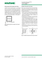
Fire-resistant damper model BKA-Ü Technical documentation Installation details Minimum gap size with complete mortar lining Installation with partial mortar lining Installation of the fire-resistant damper in an existing wall recess or a wall recess to be constructed. It has to be designed in such a way that the minimum gap size between the housing and solid wall smin is 40 mm (maximum gap size smax ≤ 60 mm). The gap "s" must be completely filled with mortar of category M2.5 to M15 to EN 998-2, NM II to III DIN V 18580 (previously: MG II to III to DIN 1053) or fire protection mortar of suitable...
Open the catalog to page 7
Fire-resistant damper model BKA-Ü Technical documentation Installation details Installation in solid ceilings Installation in solid ceilings made, for example, of concrete, aerated concrete, apparent density ≥ 500 kg/m³ and ceiling thickness D ≥ 125 mm. When installing in solid ceilings, the dimensions of the fireresistant damper BKA-Ü are limited to W and H = 500 mm. Installation of no more than 2 BKA-Üs next to each other "flange-to-flange" without clearance in solid walls. The circumferential gaps and the gap between the housing of BKA-Ü must be filled completely to the minimum ceiling...
Open the catalog to page 8
Fire-resistant damper model BKA-Ü Technical documentation Installation details Installation in lightweight partition walls with metal posts and panelling on both sides Wet installation (circumferential mortar lining) Installation without mounting frame ER in lightweight partition walls with metal posts and panelling on both sides (gypsum-bonded wall boards; wall thickness W≥ 100 mm) as classified according to EN 13501-2 or comparable national standards. No additional, permanent suspensions or attachments of BKA-Ü are allowed, and installation and mounting aids must be removed. The distance...
Open the catalog to page 9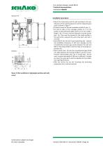
Fire-resistant damper model BKA-Ü Technical documentation Installation details Installation procedure Mount the metal posts and the wall according to the specifications of the wall manufacturer and the required spare parts as shown in Figure 7. Provide a recess for the wet installation of BKA-Ü (pos. 1) On both B sides of the exchange profiles (in ⅓ of the points), 2 bent perforated plates each (t ≥ 0.5 mm; width x length = 40 x 70 mm), must be fastened as mortar anchor (pos. 14). They must be screwed to the metal profiles in the wall centre, using one dry-wall screw each, and cast in concrete....
Open the catalog to page 10
Fire-resistant damper model BKA-Ü Technical documentation Installation details Installation procedure The general information regarding installation without mounting frame ER in lightweight partition walls with metal posts and panelling on both sides (gypsum-bonded wall boards; wall thickness W≥ 100 mm) as classified according to EN 13501-2 or comparable national standards must be observed. Mount the metal posts of the wall in accordance with the specifications of the wall manufacturer and the required spare parts as shown in Figure 7. Insert BKA-Ü (pos. 1) into the wall recess (operating...
Open the catalog to page 11All SCHAKO KG catalogs and technical brochures
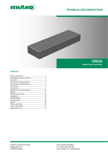 CNVA
CNVA32 Pages
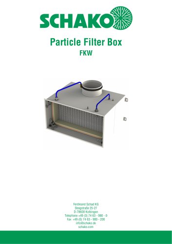 FKW (2025)
28 Pages
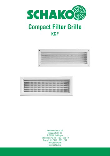 KGF Compact Filter Grille
9 Pages
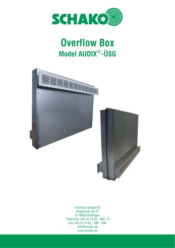
 AUDIX
AUDIX2 Pages
 DISA
DISA4 Pages
 UC-OH²
2 Pages
 IGA
IGA2 Pages
 CDD
CDD2 Pages
 FBS
FBS18 Pages
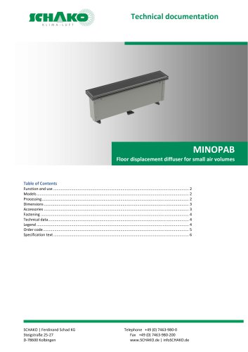 MINOPAB (2025)
6 Pages
 PIL
PIL23 Pages
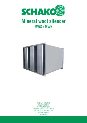 MWS / MWK
23 Pages
 ERK-SO
43 Pages
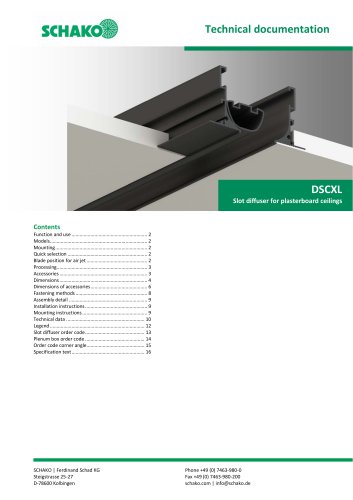 DSCXL
DSCXL17 Pages
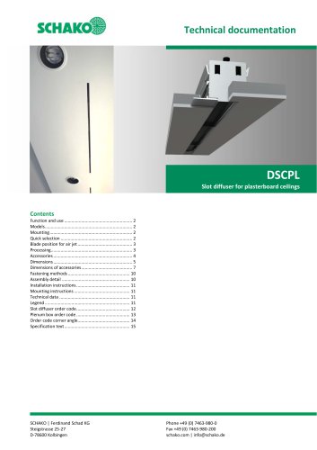 DSCPL
DSCPL16 Pages
 BKSYS
BKSYS18 Pages
 MINODSA
6 Pages
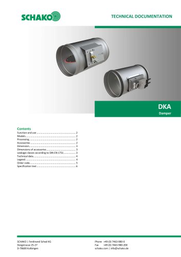 DKA
DKA6 Pages
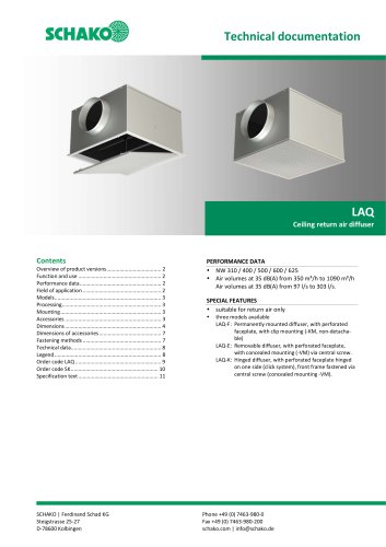 LAQ
LAQ11 Pages
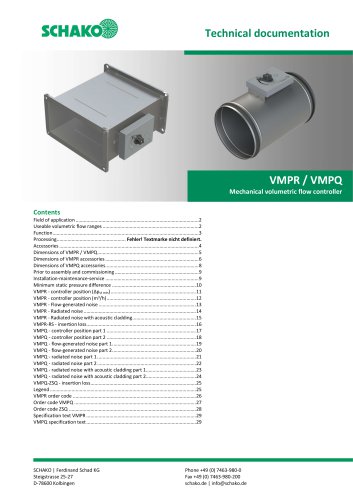 VMPR/VMPQ
29 Pages
 DSCU
DSCU18 Pages
 DSCP
DSCP15 Pages
 DQJP
DQJP9 Pages
 BKA-EN
79 Pages
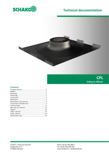 CPL
CPL15 Pages
 AUDIX®
25 Pages
 VREX
VREX26 Pages
 VQEX
VQEX17 Pages
 VPEX
VPEX18 Pages
 SVA-FS
11 Pages
 NRWG
NRWG22 Pages
 COMBIDSC
26 Pages
 DSC
DSC37 Pages
 DO
DO10 Pages
 VRAQ
VRAQ46 Pages
 UEKU
UEKU6 Pages
 UEK
UEK6 Pages
 SS-K
SS-K6 Pages
 VOLKOM
6 Pages
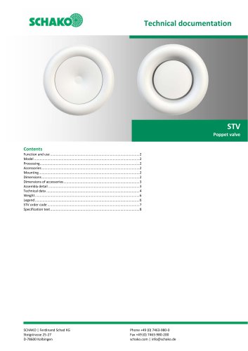 STV
STV8 Pages
 DQJ
DQJ38 Pages
 ALAS-F 125
6 Pages
 ALPETY
16 Pages
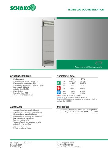 CTT
CTT23 Pages
 KWB
KWB19 Pages
 GREENKIT
20 Pages
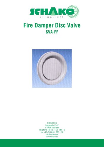
 SVA-FF
15 Pages
 FKU
FKU31 Pages
 FKF
FKF29 Pages
 SGA
SGA5 Pages
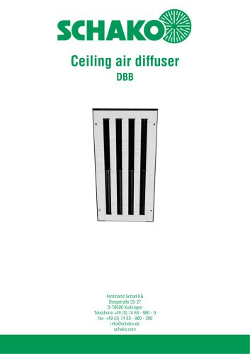 DBB
DBB27 Pages
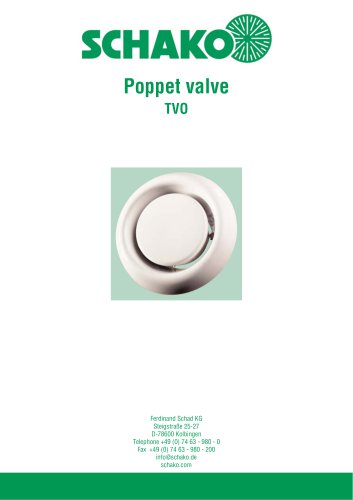 TVO
TVO8 Pages
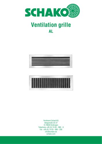 AL
AL23 Pages
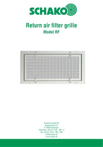
 RF Return air filter grille
7 Pages
 NBS
NBS34 Pages
 MKAR_MKAQ
13 Pages
 KF
KF4 Pages
 JK
JK16 Pages
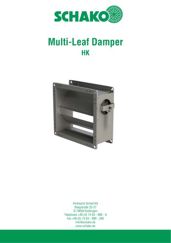 HK
HK16 Pages
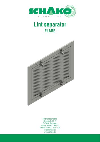
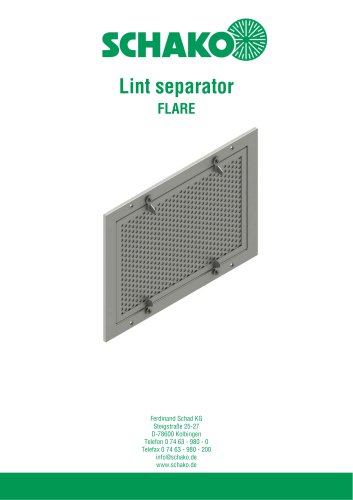 Lint Separator FLARE
13 Pages
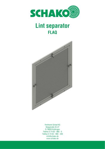 FLAQ
FLAQ11 Pages
 FG
FG14 Pages
 ERK-MB
38 Pages
 DISA-H (2025)
34 Pages
 DISA-360
32 Pages
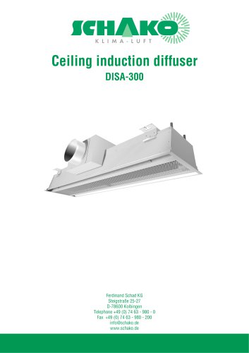 DISA-300
51 Pages
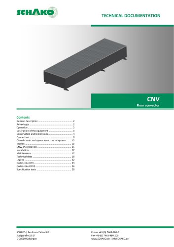 CNV
CNV29 Pages
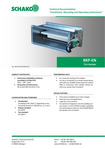
 BKP-EN Fire damper
40 Pages
 BKA-UE
35 Pages
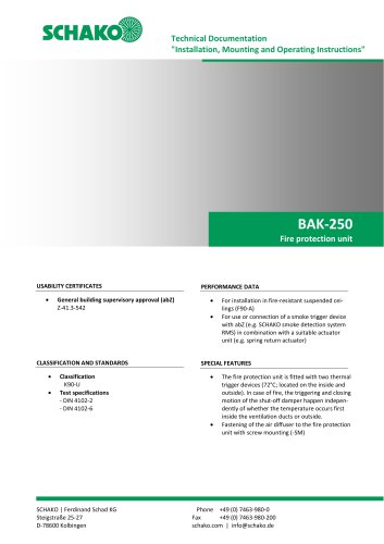 BAK-250 Fire protection unit
17 Pages
 BAK-240
16 Pages
 Aquaris-Silent
38 Pages
 Aquaris_KWB
20 Pages
 DISA-W
43 Pages
 CULTRA-Studioline
24 Pages
 BDA
BDA11 Pages
 PILB/PILBR
33 Pages
 DAV
DAV19 Pages
 4DE
4DE18 Pages
 4DF
4DF13 Pages
 DQC
DQC16 Pages
 DQDL
DQDL16 Pages
 IDA
IDA21 Pages
 IKA
IKA23 Pages
 ZMD
ZMD17 Pages
 DQF
DQF15 Pages
 DQJF
DQJF12 Pages
 DQJA/DQJR
10 Pages
 DQJSL
DQJSL17 Pages
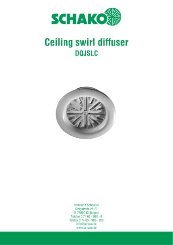 DQJSLC
17 Pages
 DHV
DHV18 Pages
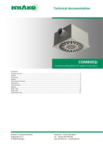 COMBIDQJ
11 Pages
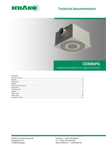 COMBIPIL
11 Pages
 DSA
DSA15 Pages
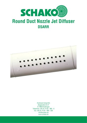 DSARR
DSARR7 Pages
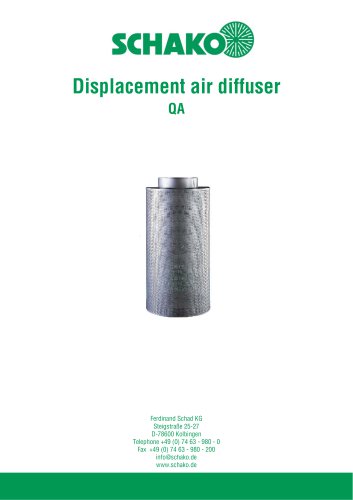 QA
QA30 Pages
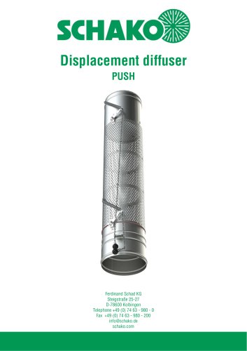 PUSH
PUSH23 Pages
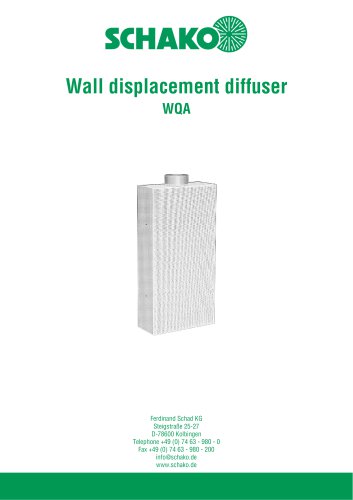 WQA
WQA12 Pages
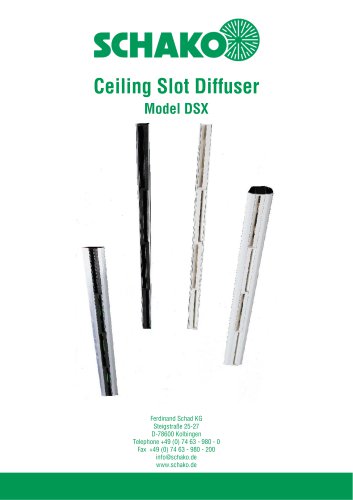 DSX
DSX25 Pages
 DSX-XXL
23 Pages
 AUDIX®-AW
20 Pages
 AUDIX®-ÜSG
13 Pages
 DSX-XXL-W
25 Pages
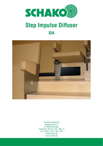 SIA
SIA7 Pages
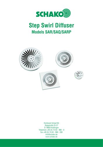 SAR/SAQ/SARP
13 Pages
 WDA
WDA32 Pages
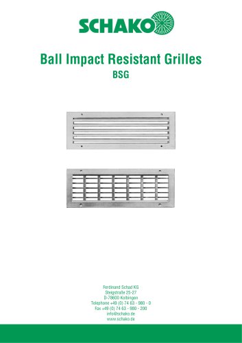 BSG
BSG19 Pages
 KG
KG19 Pages
 IB-Q
IB-Q21 Pages
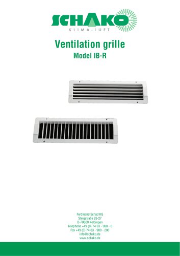 IB-R
IB-R15 Pages
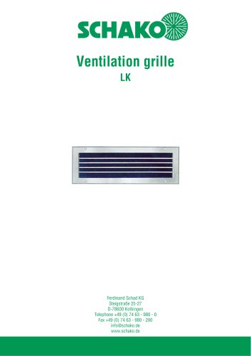 LK
LK12 Pages
 PA
PA32 Pages
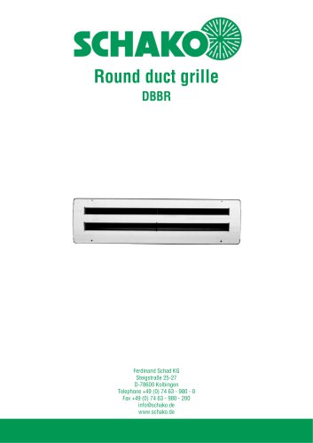 DBBR
DBBR6 Pages
 KGRR
KGRR17 Pages
 DBBRR
DBBRR11 Pages
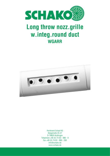 WGARR
WGARR7 Pages
 WGA
WGA29 Pages
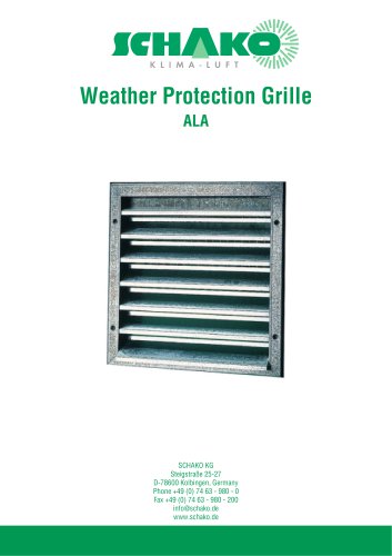 ALA
ALA4 Pages
 ALA-R
ALA-R4 Pages
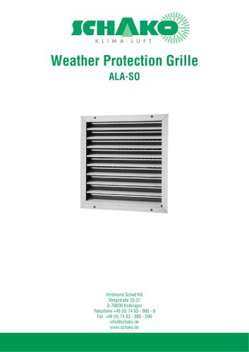 ALA-SO
4 Pages
 ALAS
ALAS10 Pages
 ALAS-P
5 Pages
 DKAPPs
6 Pages
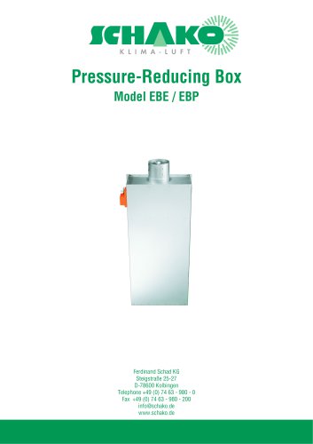 EBE/EBP
52 Pages
 DKG
DKG6 Pages
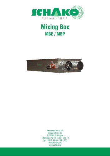 MBE/MBP
27 Pages
 PIANO
PIANO27 Pages
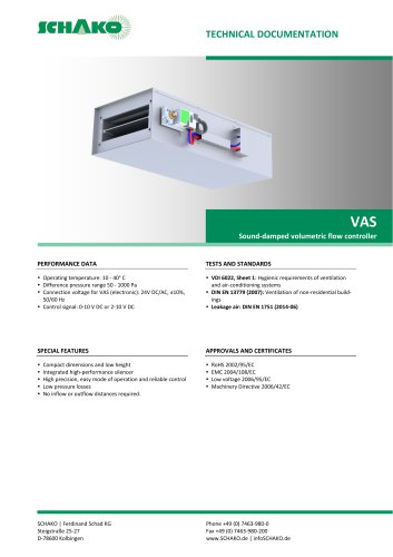 VAS
VAS26 Pages
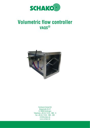 VAQS
VAQS19 Pages
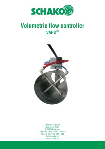 VARS
VARS26 Pages
 VRAPPs
20 Pages
 VRAR
VRAR52 Pages
 MAK
MAK15 Pages
 RS-F
RS-F7 Pages
 RS
RS15 Pages
 EasyBus
24 Pages
 DISA-Family
4 Pages
 RMS
RMS11 Pages
 TSR
TSR5 Pages
 VLV
VLV31 Pages
 MBM
MBM10 Pages
 LL
LL7 Pages
 RR-Complete
41 Pages
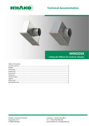 MINODSX
6 Pages
 SPB
SPB10 Pages
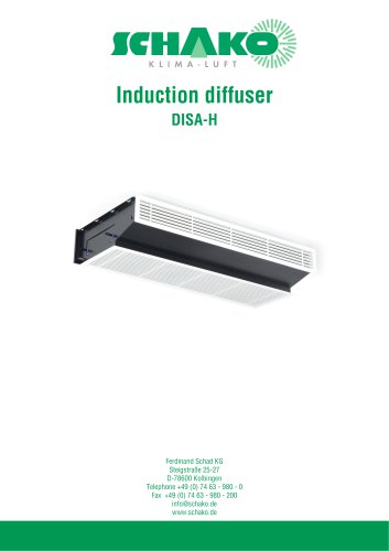 DISA-H
34 Pages
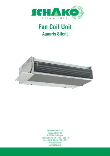 AQUARIS SILENT
38 Pages
 NBS
NBS24 Pages
 JK-LP/JK-LU
15 Pages
 HKP / HKU
16 Pages
 FKW
FKW16 Pages
 FLARE
FLARE13 Pages
 RF
RF7 Pages
 KGF
KGF9 Pages
 SVA-FF
8 Pages
 BSK-RPR
60 Pages
 BKP-EN
40 Pages
 BAK-240
6 Pages
 BAK-250
14 Pages


- Ventilation grill
- Industrial air conditioner
- Metal ventilation grill
- Rectangular ventilation grill
- Commercial detector
- Commercial air conditioning cabinet
- Industrial air diffuser
- Reversible air conditioner
- Aluminum ventilation grill
- Exterior ventilation grill
- Commercial ventilation grill
- Facade ventilation grill
- Ceiling-mounted air diffuser
- Industrial fan coil
- White ventilation grill
- Industrial convector
- Home ventilation grill
- Metal convector
- Contemporary convector
- Wall-mounted air conditioner