- Company
- Products
- Catalogs
- News & Trends
- Exhibitions
BKA-EN
1 /79Pages

BKA-EN
1 /79Pages
Catalog excerpts

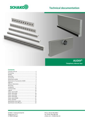
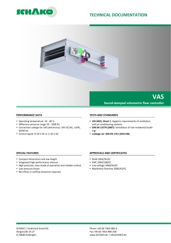
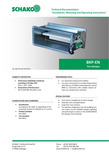
Technical Documentation "Installation, Mounting and Operating Instruc- BKA-EN Fire damper Fig.: BKA-EN with B10 drive USABILITY CERTIFICATES PERFORMANCE DATA • Declaration of Performance • For automatic locking of fire lobbies DoP-BKA-EN-2020-07-10 • For use or connection of a smoke release device with abZ (e.g. SCHAKO smoke detection system RMS) in connection with suitable release devices (e.g. spring return actuator) • Classification according to EN 13501-3, depending on the mounting situation EI 30 (ve, iOo) S to EI 90 (ve, ho iOo) S • Product standard EN 15650 • Test standard EN 1366-2 SPECIAL FEATURES • ATEX version available (at an extra charge) • Extensive uses and applications • Large free cross-sections • For optimum integration into the building control system via the SCHAKO EasyBus signalling and switching bus system or the SCHAKO BKSYS fire damper mini-controller SCHAKO | Ferdinand Schad KG SteigstraRe 25-27 D-78600 Kolbingen
Open the catalog to page 1
Fire damper BKA-EN Technical documentation Table of Contents Construction subject to change No return possible
Open the catalog to page 2
Fire damper BKA-EN Technical documentation Description DESCRIPTION Fire dampers built into ventilation ducts (air-conditioning systems) are used for the automatic locking of fire lobbies. The fire damper BKA-EN conforms to EN 15650, EN 13501-3 and EN 1366-2. The BKA-EN has been tested in compliance with EN 1366-2 according to the Declaration of performance no. DoP-BKA-EN-2020-07-10. Its classification according to EN 13501-3 is EI 30 (ve, i↔o) S to EI 90 (ve, ho i↔o) S. According to Directive 2014/34/EU, EC Certificate of Conformity number EPS 09 ATEX 2 153 X, its use in areas subject to explosion...
Open the catalog to page 3
Fire damper BKA-EN Technical documentation Models and dimensions - Housing length L = 375 or 500 mm (standard). - All width and height dimensions can be combined. - Trigger device always on H side. - Inspection opening always on B side. - On request, the width and height dimensions (B, H) are available in steps of 10 mm. Construction subject to change No return possible
Open the catalog to page 4
Fire damper BKA-EN Technical documentation Models and dimensions "a" = 50 mm: Minimum distance between the front edge of the open damper blade and the finishing protective grating (ASG), the flexible connection piece (FS) or the duct connection spigot (RS). SCHAKO ASG/VT/FS/RS: Flange holes suitable for BKA-EN Figure 2: Frame bores * Extension piece (VT) necessary Table 2: Damper blade projecting ends Construction subject to change No return possible Version: 2020-07-10 | Page 5
Open the catalog to page 5
Fire damper BKA-EN Technical documentation Models and dimensions Use The fire damper type BKA-EN can be installed as shown in the following tables. Additional note: It may also be installed in and on walls or in and on ceilings of a lower fire resistance class. In this case, however, the fire resistance class of the fire damper is reduced. The conditions listed above must be taken into account. 1 If mineral wool is used between the fire dampers, the distance between them is 80 mm. 3) The additional frame (installation/mounting kit) can only be used with BKA-EN L=375. 4) Depending on the mounting...
Open the catalog to page 6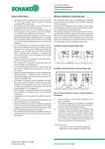
Fire damper BKA-EN Technical documentation Models and dimensions General information Minimum distances or projecting ends The dimensions given must be considered an installation recommendation for the BKA-EN and may differ, depending on the local situation. To guarantee fire protection, the fire damper must be installed in accordance with the technical documentation, installation, mounting and operating instructions. The inspection openings of the fire damper must be freely accessible, otherwise these inspection openings must be provided in the connected ventilation ducts in the immediate proximity....
Open the catalog to page 7
Fire damper BKA-EN Technical documentation Installation in solid walls The dimension x is: - approx. 85 mm with manual release, magnetic clamps MH1/MH2, pulse magnets MI1/MI2, spring return actuators S00/S01/S10/S11/S20/S21 - approx. 90 mm with spring return actuators B10/B11/B20/B21/B32/B33/B42 - max. approx. 170 mm with explosion-protected spring return actuator ExMax-5.10-BF (X10 - X15) - approx. 175 mm with pneumatics (without limit switch) INSTALLATION IN SOLID WALLS Installation in solid walls (shaft walls, shafts, ducts and fire walls) made of, for example, concrete; masonry according...
Open the catalog to page 8
Fire damper BKA-EN Technical documentation Installation in solid walls Installation next to each other Wet installation of a fire damper, complete mortar lining The minimum distance of fire dampers from one another must be at least 70 mm. The minimum distance to adjacent components (wall/ceiling) is 40 mm. Figure 8: Installation in solid walls at a reduced distance "flange-to-flange", next to each other Figure 6: Annular gap size for complete mortar lining in solid walls Wet installation with rigid ceiling connection, partial mortar lining Wet installation at a reduced distance "flange...
Open the catalog to page 9
Fire damper BKA-EN Technical documentation Installation in solid walls Wet installation with installation kit type GDA, flexible ceiling connection • • If the installation kit type GDA is used, only a BKA-EN with a housing length of L=375 is possible. Installation with installation kit type GDA in the area of flexible ceiling connections (flexibility/ceiling bending ≤ 20 mm). The installation kit type GDA (pos. 35) or the optional doubling (pos. 36) must be positioned at the same height as the wall head area (see Figure 10; “x“), the mineral wool will be pressed. Steel profiles belonging to the...
Open the catalog to page 10
Fire damper BKA-EN Technical documentation Installation in solid walls Figure 12: Distance to the solid ceiling The fire damper (pos. 1) is installed after the construction of the wall and the correct installation opening. The ground (bottom side of the ceiling) must be even, bigger unevenness must be levelled (e.g. plaster filling). Prior to the installation, the mineral wool of the installation kit type GDA (pos. 35) has to be cut to the correct length according to the existing installation opening and must be placed on the installation kit type GDA. Place the installation kit type GDA in the...
Open the catalog to page 11All SCHAKO KG catalogs and technical brochures
 CNVA
CNVA32 Pages
 FKW (2025)
28 Pages
 KGF Compact Filter Grille
9 Pages
 AUDIX
AUDIX2 Pages
 DISA
DISA4 Pages
 UC-OH²
2 Pages
 IGA
IGA2 Pages
 CDD
CDD2 Pages
 FBS
FBS18 Pages
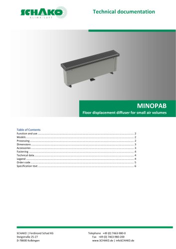 MINOPAB (2025)
6 Pages
 PIL
PIL23 Pages
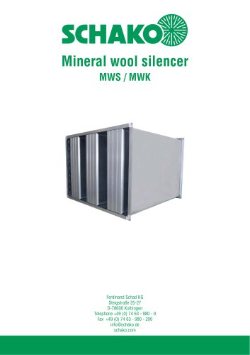 MWS / MWK
23 Pages
 ERK-SO
43 Pages
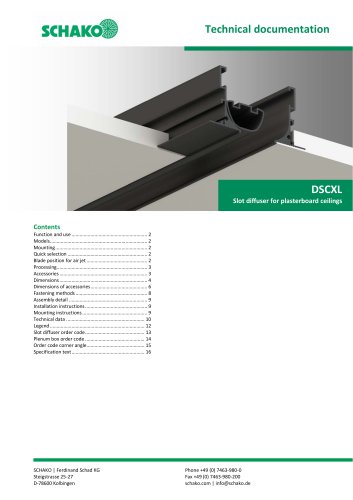 DSCXL
DSCXL17 Pages
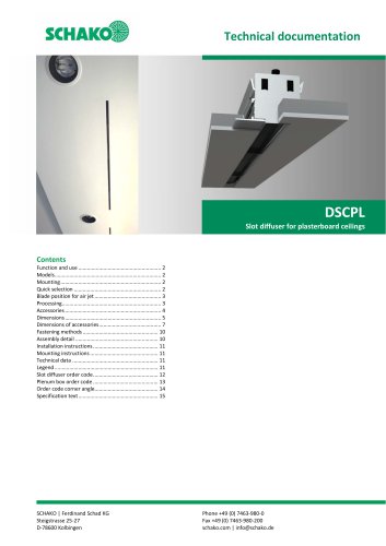 DSCPL
DSCPL16 Pages
 BKSYS
BKSYS18 Pages
 MINODSA
6 Pages
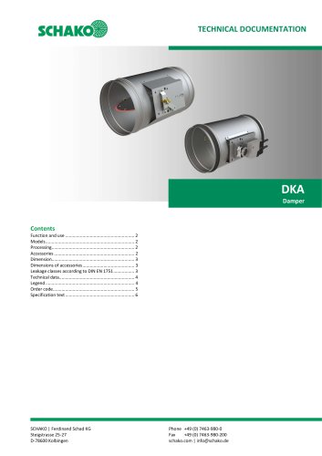 DKA
DKA6 Pages
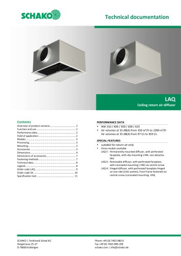 LAQ
LAQ11 Pages
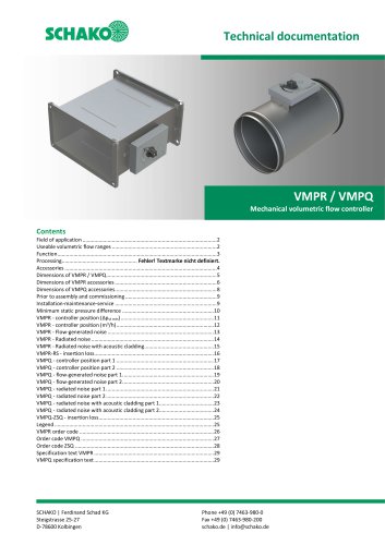 VMPR/VMPQ
29 Pages
 DSCU
DSCU18 Pages
 DSCP
DSCP15 Pages
 DQJP
DQJP9 Pages
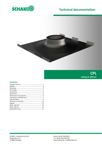 CPL
CPL15 Pages
 AUDIX®
25 Pages
 VREX
VREX26 Pages
 VQEX
VQEX17 Pages
 VPEX
VPEX18 Pages
 SVA-FS
11 Pages
 NRWG
NRWG22 Pages
 COMBIDSC
26 Pages
 DSC
DSC37 Pages
 DO
DO10 Pages
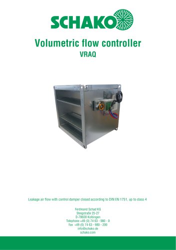 VRAQ
VRAQ46 Pages
 UEKU
UEKU6 Pages
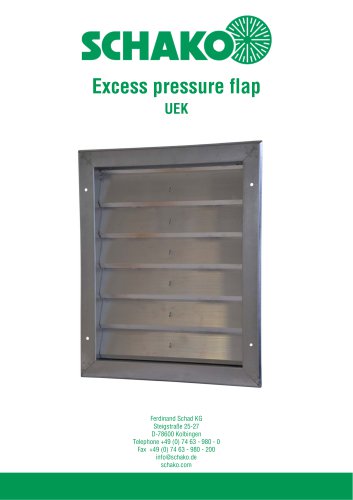 UEK
UEK6 Pages
 SS-K
SS-K6 Pages
 VOLKOM
6 Pages
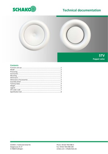 STV
STV8 Pages
 DQJ
DQJ38 Pages
 ALAS-F 125
6 Pages
 ALPETY
16 Pages
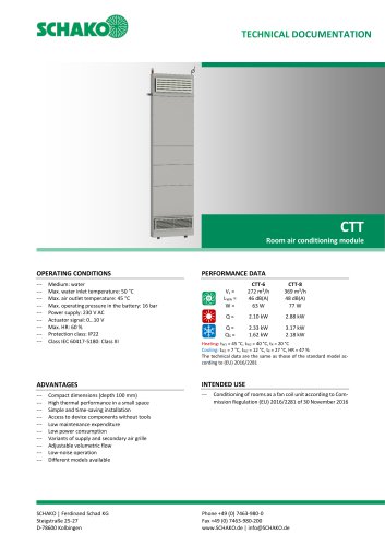 CTT
CTT23 Pages
 KWB
KWB19 Pages
 GREENKIT
20 Pages
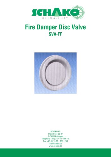
 SVA-FF
15 Pages
 FKU
FKU31 Pages
 FKF
FKF29 Pages
 SGA
SGA5 Pages
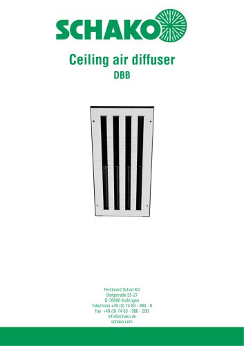 DBB
DBB27 Pages
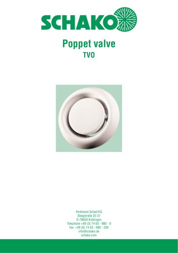 TVO
TVO8 Pages
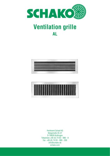 AL
AL23 Pages
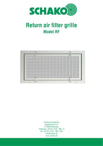
 RF Return air filter grille
7 Pages
 NBS
NBS34 Pages
 MKAR_MKAQ
13 Pages
 KF
KF4 Pages
 JK
JK16 Pages
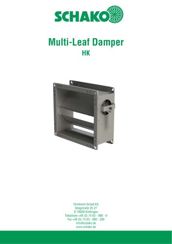 HK
HK16 Pages
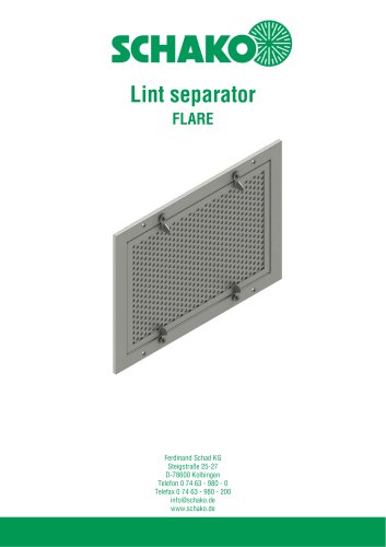 Lint Separator FLARE
13 Pages
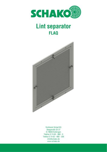 FLAQ
FLAQ11 Pages
 FG
FG14 Pages
 ERK-MB
38 Pages
 DISA-H (2025)
34 Pages
 DISA-360
32 Pages
 DISA-300
51 Pages
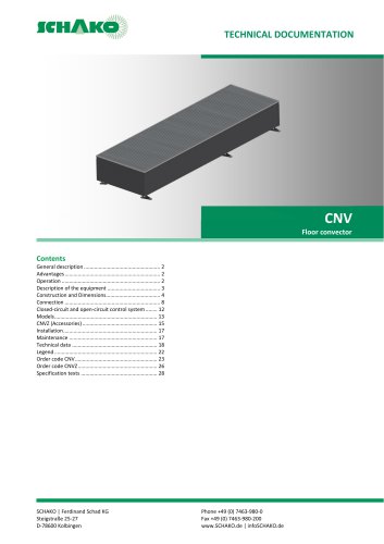 CNV
CNV29 Pages
 BKP-EN Fire damper
40 Pages
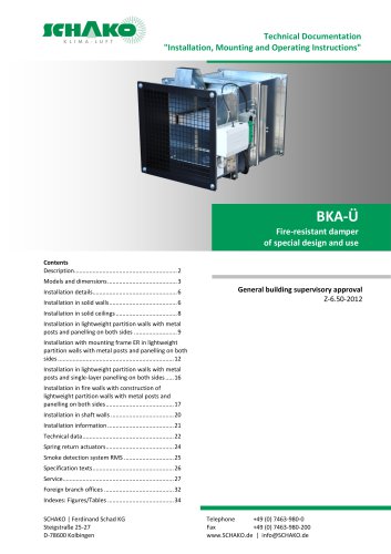 BKA-UE
35 Pages
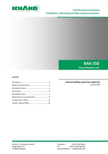
 BAK-250 Fire protection unit
17 Pages
 BAK-240
16 Pages
 Aquaris-Silent
38 Pages
 Aquaris_KWB
20 Pages
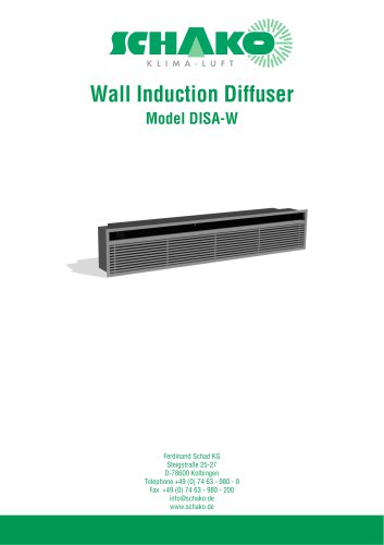 DISA-W
43 Pages
 CULTRA-Studioline
24 Pages
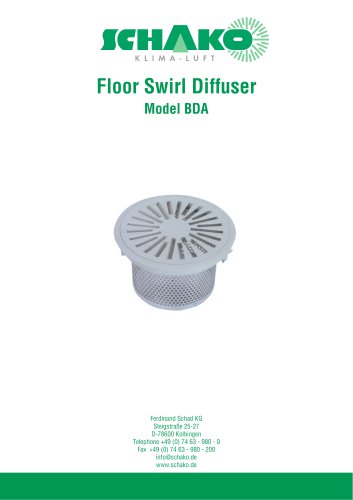 BDA
BDA11 Pages
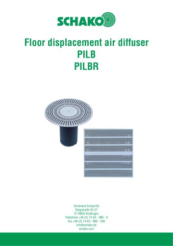 PILB/PILBR
33 Pages
 DAV
DAV19 Pages
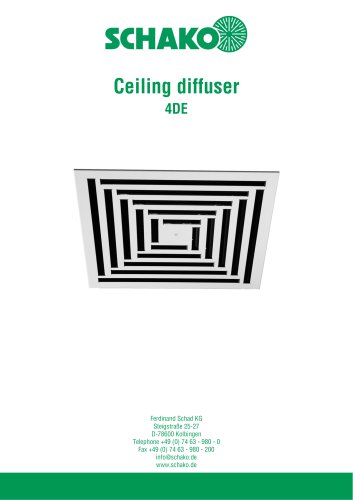 4DE
4DE18 Pages
 4DF
4DF13 Pages
 DQC
DQC16 Pages
 DQDL
DQDL16 Pages
 IDA
IDA21 Pages
 IKA
IKA23 Pages
 ZMD
ZMD17 Pages
 DQF
DQF15 Pages
 DQJF
DQJF12 Pages
 DQJA/DQJR
10 Pages
 DQJSL
DQJSL17 Pages
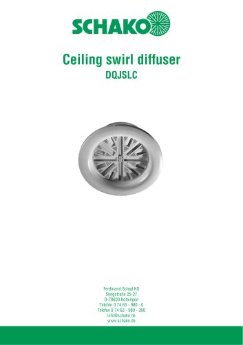 DQJSLC
17 Pages
 DHV
DHV18 Pages
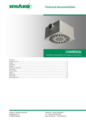 COMBIDQJ
11 Pages
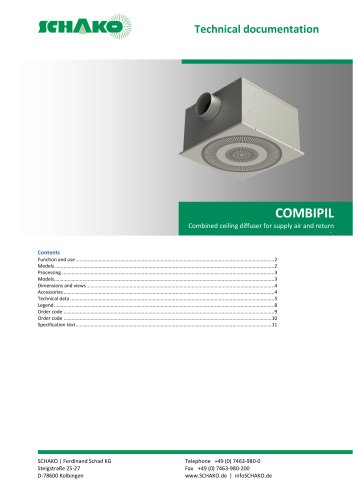 COMBIPIL
11 Pages
 DSA
DSA15 Pages
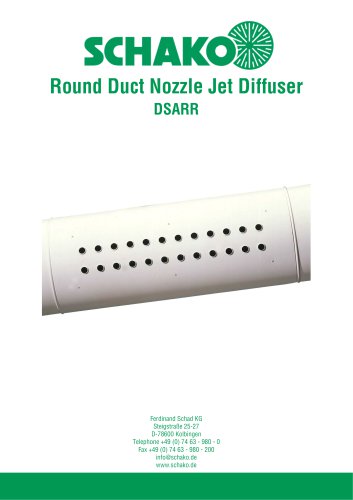 DSARR
DSARR7 Pages
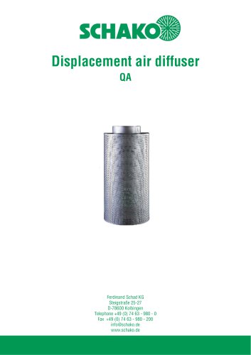 QA
QA30 Pages
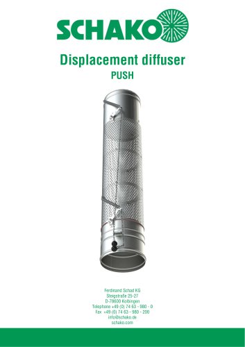 PUSH
PUSH23 Pages
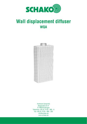 WQA
WQA12 Pages
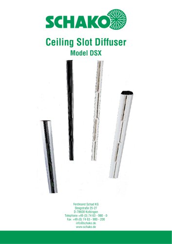 DSX
DSX25 Pages
 DSX-XXL
23 Pages
 AUDIX®-AW
20 Pages
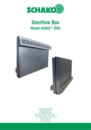 AUDIX®-ÜSG
13 Pages
 DSX-XXL-W
25 Pages
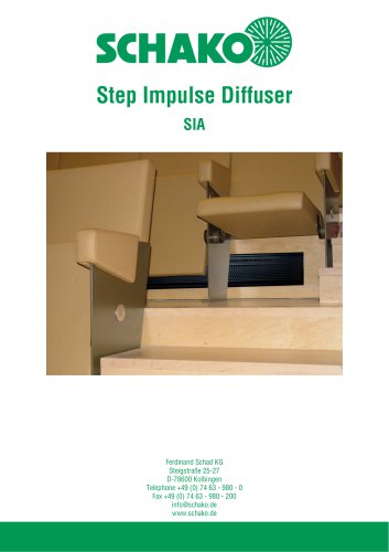 SIA
SIA7 Pages
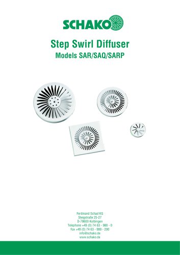 SAR/SAQ/SARP
13 Pages
 WDA
WDA32 Pages
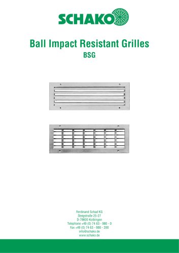 BSG
BSG19 Pages
 KG
KG19 Pages
 IB-Q
IB-Q21 Pages
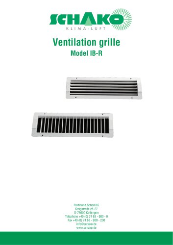 IB-R
IB-R15 Pages
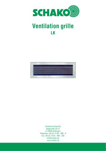 LK
LK12 Pages
 PA
PA32 Pages
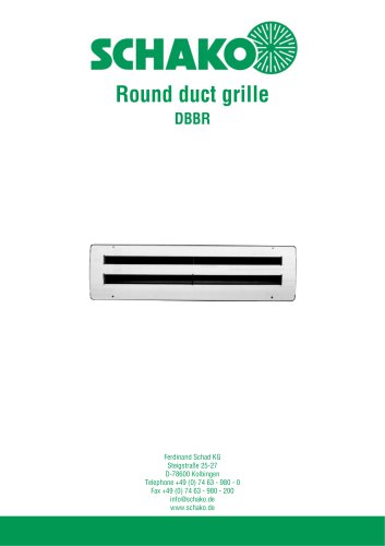 DBBR
DBBR6 Pages
 KGRR
KGRR17 Pages
 DBBRR
DBBRR11 Pages
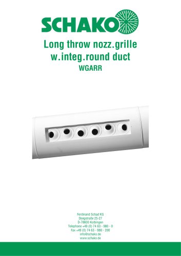 WGARR
WGARR7 Pages
 WGA
WGA29 Pages
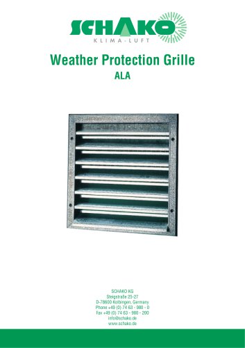 ALA
ALA4 Pages
 ALA-R
ALA-R4 Pages
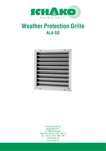 ALA-SO
4 Pages
 ALAS
ALAS10 Pages
 ALAS-P
5 Pages
 DKAPPs
6 Pages
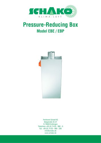 EBE/EBP
52 Pages
 DKG
DKG6 Pages
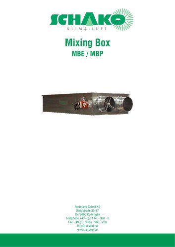 MBE/MBP
27 Pages
 PIANO
PIANO27 Pages
 VAS
VAS26 Pages
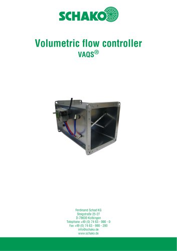 VAQS
VAQS19 Pages
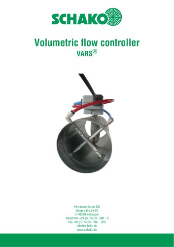 VARS
VARS26 Pages
 VRAPPs
20 Pages
 VRAR
VRAR52 Pages
 MAK
MAK15 Pages
 RS-F
RS-F7 Pages
 RS
RS15 Pages
 EasyBus
24 Pages
 DISA-Family
4 Pages
 RMS
RMS11 Pages
 TSR
TSR5 Pages
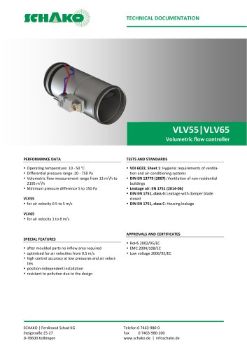 VLV
VLV31 Pages
 MBM
MBM10 Pages
 LL
LL7 Pages
 RR-Complete
41 Pages
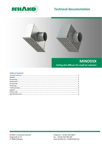 MINODSX
6 Pages
 SPB
SPB10 Pages
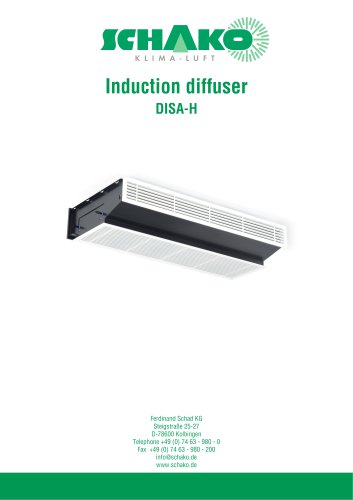 DISA-H
34 Pages
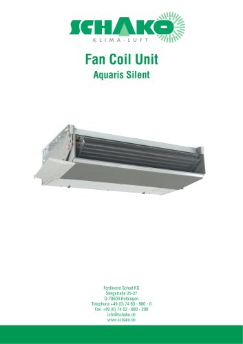 AQUARIS SILENT
38 Pages
 NBS
NBS24 Pages
 JK-LP/JK-LU
15 Pages
 HKP / HKU
16 Pages
 FKW
FKW16 Pages
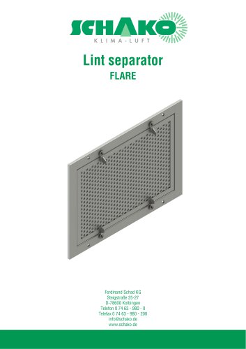 FLARE
FLARE13 Pages
 RF
RF7 Pages
 KGF
KGF9 Pages
 SVA-FF
8 Pages
 BKA-Ü
BKA-Ü35 Pages
 BSK-RPR
60 Pages
 BKP-EN
40 Pages
 BAK-240
6 Pages
 BAK-250
14 Pages


- Ventilation grill
- Industrial air conditioner
- Metal ventilation grill
- Rectangular ventilation grill
- Commercial detector
- Commercial air conditioning cabinet
- Industrial air diffuser
- Reversible air conditioner
- Aluminum ventilation grill
- Exterior ventilation grill
- Commercial ventilation grill
- Facade ventilation grill
- Ceiling-mounted air diffuser
- Industrial fan coil
- White ventilation grill
- Industrial convector
- Home ventilation grill
- Metal convector
- Contemporary convector
- Wall-mounted air conditioner