- Company
- Products
- Catalogs
- News & Trends
- Exhibitions
BAK-240
1 /16Pages

BAK-240
1 /16Pages
Catalog excerpts

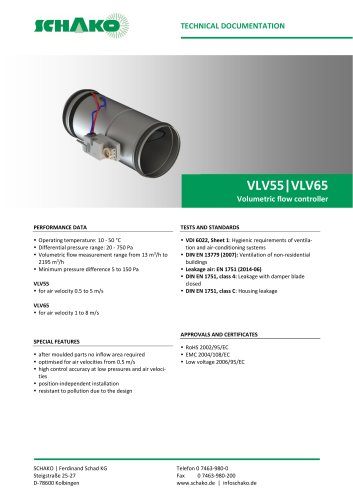
Technical Documentation "Installation, Mounting and Operating Instructions" BAK-240 Fire protection unit USABILITY CERTIFICATE • General building supervisory approval (abZ) Z-41.3-574 Classification K30-U Test specifications - DIN 4102-2 - DIN 4102-6 PERFORMANCE DATA • SPECIAL FEATURES • SCHAKO | Ferdinand Schad KG Steigstraße 25-27 D-78600 Kolbingen For installation into fire-resistant suspended ceilings (F30-A) The fire protection unit is fitted with two thermal trigger devices (72°C; located on the inside and outside). In case of fire, the triggering and the closing motion of the shut-off damper happen independently of whether the temperature occurs first inside the ventilation ducts or outside. Fastening of the air diffuser to the suspended ceiling or fire protection unit with screw mounting (-SM).
Open the catalog to page 1
Fire protection unit BAK-240 Technical documentation Table of Contents Construction subject to change No return possible
Open the catalog to page 2
Fire protection unit BAK-240 Technical documentation Description VENTILATION FITTINGS Openings for ventilation ducts in fire-resistant suspended ceilings must be sealed against fire and smoke by means of shutoff devices. The shut-off device type BAK-240 (hereafter referred to as fire protection unit type BAK-240), of resistance class K30-U, according to general building approval (abZ) No. Z-41.3-574 is suitable for installation in fire-resistant suspended ceilings. This ceiling must be designed as panelled ceiling in screw-type and spatulated design and must meet the requirements of an independent...
Open the catalog to page 3
Fire protection unit BAK-240 Technical documentation Description CONNECTION OF VENTILATION DUCTS The fire protection unit type BAK-240 must only be connected to non-flammable ventilation ducts. The local regulations or national standards on ventilation systems (in Germany e.g. M-LüAR, in the locally applicable version) apply. No inadmissible forces may affect the fire protection unit and suspended ceiling especially in case of fire and impair their fire resistance time. The required expansion joints (flexible spigots) must be designed as flammable, elastic spigots made of at least standard inflammable...
Open the catalog to page 4
Fire protection unit BAK-240 Technical documentation Models and dimensions MODELS AND DIMENSIONS 1 Housing 2 Shut-off damper 3 Trigger device 4 Fusible link inside 5 Fusible link outside 6 Trigger clip 7 Catch spring 8 Limit switch (optional) 9 Protective cover 10 Shut-off steel sheet Available sizes Nominal size * It is also possible to select a smaller spigot diameter 0D 1 External dimensions Table 1: Available sizes Construction subject to change No return possible Version: 2019-12-01 | Page 5
Open the catalog to page 5
Fire protection unit BAK-240 Technical documentation Installation details Release device As standard, the fire protection unit is supplied with an inside and outside thermal trigger device (fusible link with 72°C trigger temperature)! Thus, in case of fire, the triggering and closing motion of the shut-off damper happen independently of whether the temperature > 72°C occurs first on the inside or outside of the duct system. The breakage of one of the fusible links closes the shut-off damper and locks it into place. The fusible link must be replaced before the shut-off damper can be locked in...
Open the catalog to page 6
Fire protection unit BAK-240 Technical documentation Accessories Mounting Screw mounting (-SM), countersunk screws (4, on site). The only possible fastening type is screw mounting. ACCESSORIES Available at an extra charge Limit switch type ES-1A (-ESA) Electric limit switch for position indication. Switching element including one NC and one NO contact each, 4 connections for M3,5 screw terminals for max. 2 mm². 250 V AC, Ie 6A, IP67 using suitable cable glands M20 (on-site). Air throw pattern “A“ : All blades in position 2 “B“ : Blades in position 1+2, preset ex works “C“ : Without blades (for...
Open the catalog to page 7
Fire protection unit BAK-240 Technical documentation Order code ORDER CODEBAK-240 ORDER CODE 01 EXAMPLE BAK240-44-400-158-72-HAN-ESA Type BAK240 = fire protection unit BAK-240 | Air diffuser 44 = BDQJ | Nominal size = 400 mm | Spigot diameter = 158 mm | Trigger temperature 72 = 72°C | Actuator type HAN = thermo-mechanical triggering | Accessory ESA = ES-1A (limit switch in OPEN position) ORDER DETAILS 01 - TYPE HAN = thermo-mechanical triggering 07 - ACCESSORIES Z00 = without accessories ESA = ES-1A (limit switch OPEN) Construction subject to change No return possible
Open the catalog to page 8
Fire protection unit BAK-240 Technical documentation Order code BDQJ ORDER CODE 01 EXAMPLE BDQJ-Q-SR-Z-500-SB-9010-000-PT-L9010-A-SM-A0 Type BDQJ = ceiling swirl diffuser for fire protection unit| Q = version with square faceplate | SR = circular blade pattern | Z = air throw supply air | Nominal size = 500 mm | SB = faceplate made of sheet steel | 9010 = face plate painted to RAL9010 | Drill pattern 000 = not reduced | Blades PT = divided blades | Blade colour L9010 = plastic similar to RAL 9010 white | Air throw pattern A = all blades in position 2 | Mounting SM = screw mounting | Cover A0...
Open the catalog to page 9
Fire protection unit BAK-240 Technical documentation Specification texts Fire protection unit of resistance class K30-U, according to general building supervisory approval Z-41.3-574, suitable for installation in fire-resistant suspended ceilings designed as panelled ceilings in screw-type and spatulated design that meet the requirements of an independent component of being fire-resistant for 30 minutes in the event of a fire from top or bottom. With metal-cased shut-off damper and visible screw mounting of the air diffuser. The shut-off damper is triggered by an inside and outside thermal trigger...
Open the catalog to page 10
Fire protection unit BAK-240 Technical documentation Service SERVICE Checking the function, cleaning, repair 2 Thermo-mechanical trigger device Polluted and damp air can impair the continuous operational safety. This is why, after commissioning the ventilation installation, all shut-off devices must be subjected to a functional test at a six-month interval, according to section 3.3 of the general building supervisory approval Z-41.3-574. If two consecutive functional tests show no defects, the shut-off devices only have to be tested at a yearly interval. If maintenance agreements are made for...
Open the catalog to page 11All SCHAKO KG catalogs and technical brochures
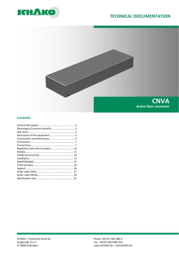 CNVA
CNVA32 Pages
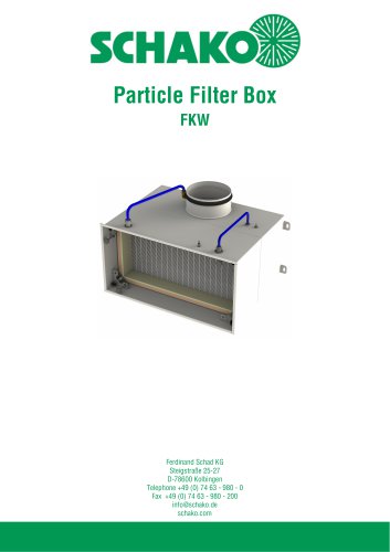 FKW (2025)
28 Pages
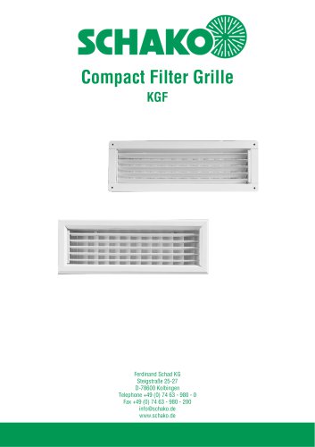 KGF Compact Filter Grille
9 Pages
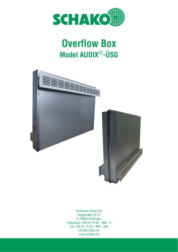
 AUDIX
AUDIX2 Pages
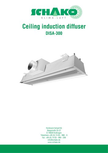
 DISA
DISA4 Pages
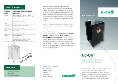 UC-OH²
2 Pages
 IGA
IGA2 Pages
 CDD
CDD2 Pages
 FBS
FBS18 Pages
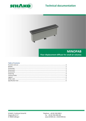 MINOPAB (2025)
6 Pages
 PIL
PIL23 Pages
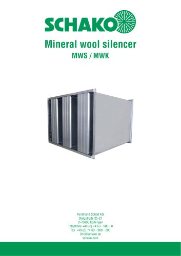 MWS / MWK
23 Pages
 ERK-SO
43 Pages
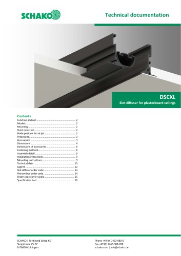 DSCXL
DSCXL17 Pages
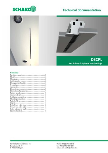 DSCPL
DSCPL16 Pages
 BKSYS
BKSYS18 Pages
 MINODSA
6 Pages
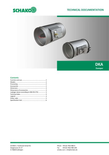 DKA
DKA6 Pages
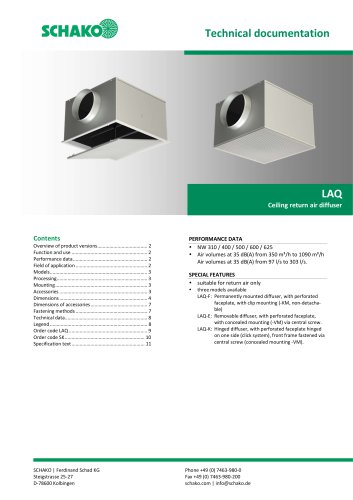 LAQ
LAQ11 Pages
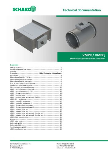 VMPR/VMPQ
29 Pages
 DSCU
DSCU18 Pages
 DSCP
DSCP15 Pages
 DQJP
DQJP9 Pages
 BKA-EN
79 Pages
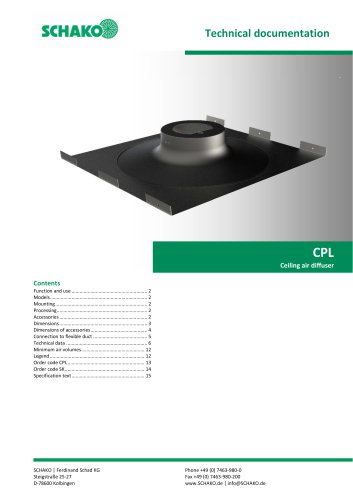 CPL
CPL15 Pages
 AUDIX®
25 Pages
 VREX
VREX26 Pages
 VQEX
VQEX17 Pages
 VPEX
VPEX18 Pages
 SVA-FS
11 Pages
 NRWG
NRWG22 Pages
 COMBIDSC
26 Pages
 DSC
DSC37 Pages
 DO
DO10 Pages
 VRAQ
VRAQ46 Pages
 UEKU
UEKU6 Pages
 UEK
UEK6 Pages
 SS-K
SS-K6 Pages
 VOLKOM
6 Pages
 STV
STV8 Pages
 DQJ
DQJ38 Pages
 ALAS-F 125
6 Pages
 ALPETY
16 Pages
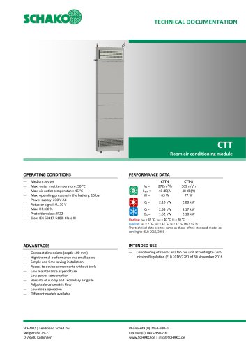 CTT
CTT23 Pages
 KWB
KWB19 Pages
 GREENKIT
20 Pages
 SVA-FF
15 Pages
 FKU
FKU31 Pages
 FKF
FKF29 Pages
 SGA
SGA5 Pages
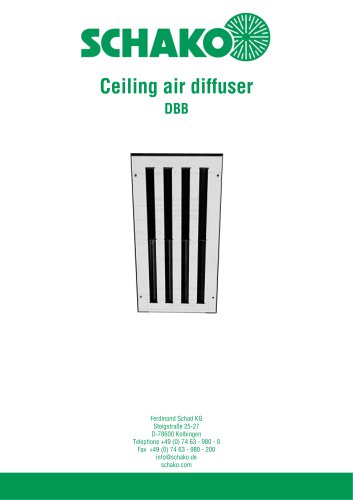 DBB
DBB27 Pages
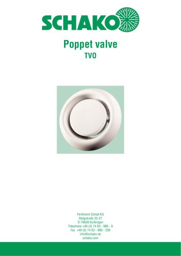 TVO
TVO8 Pages
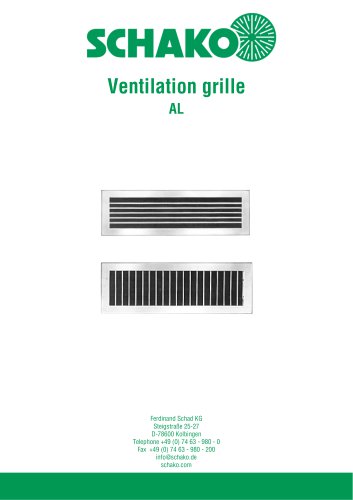 AL
AL23 Pages
 RF Return air filter grille
7 Pages
 NBS
NBS34 Pages
 MKAR_MKAQ
13 Pages
 KF
KF4 Pages
 JK
JK16 Pages
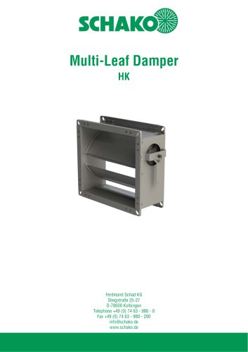 HK
HK16 Pages
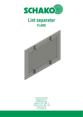 Lint Separator FLARE
13 Pages
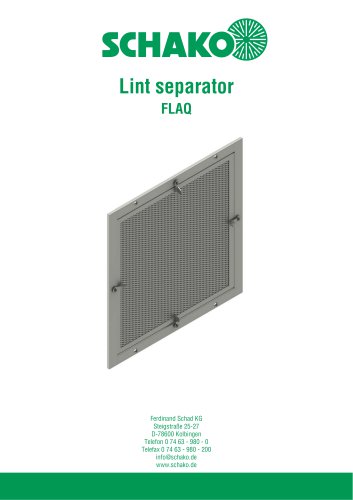 FLAQ
FLAQ11 Pages
 FG
FG14 Pages
 ERK-MB
38 Pages
 DISA-H (2025)
34 Pages
 DISA-360
32 Pages
 DISA-300
51 Pages
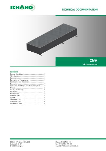 CNV
CNV29 Pages
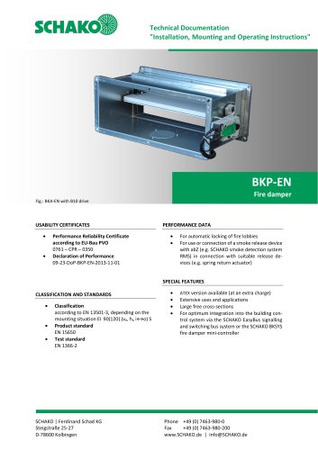
 BKP-EN Fire damper
40 Pages
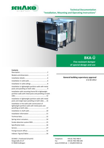 BKA-UE
35 Pages
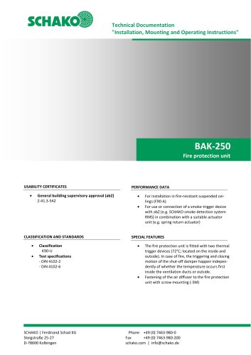 BAK-250 Fire protection unit
17 Pages
 Aquaris-Silent
38 Pages
 Aquaris_KWB
20 Pages
 DISA-W
43 Pages
 CULTRA-Studioline
24 Pages
 BDA
BDA11 Pages
 PILB/PILBR
33 Pages
 DAV
DAV19 Pages
 4DE
4DE18 Pages
 4DF
4DF13 Pages
 DQC
DQC16 Pages
 DQDL
DQDL16 Pages
 IDA
IDA21 Pages
 IKA
IKA23 Pages
 ZMD
ZMD17 Pages
 DQF
DQF15 Pages
 DQJF
DQJF12 Pages
 DQJA/DQJR
10 Pages
 DQJSL
DQJSL17 Pages
 DQJSLC
17 Pages
 DHV
DHV18 Pages
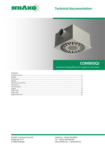 COMBIDQJ
11 Pages
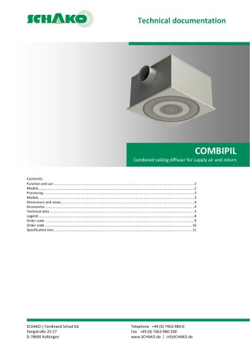 COMBIPIL
11 Pages
 DSA
DSA15 Pages
 DSARR
DSARR7 Pages
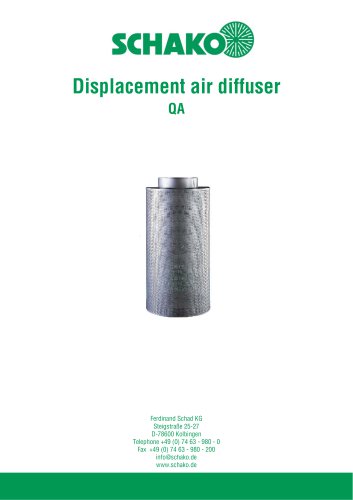 QA
QA30 Pages
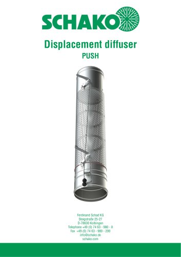 PUSH
PUSH23 Pages
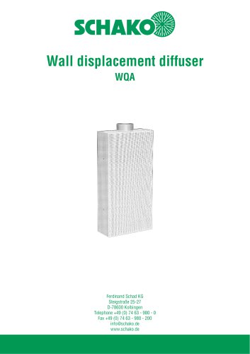 WQA
WQA12 Pages
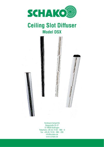 DSX
DSX25 Pages
 DSX-XXL
23 Pages
 AUDIX®-AW
20 Pages
 AUDIX®-ÜSG
13 Pages
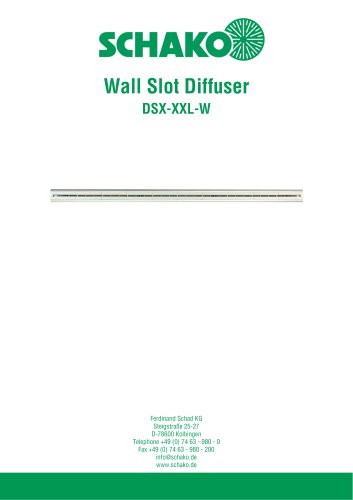 DSX-XXL-W
25 Pages
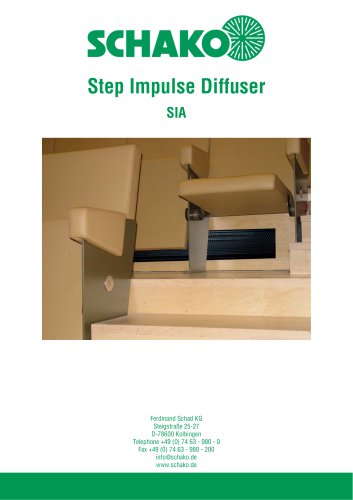 SIA
SIA7 Pages
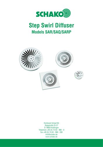 SAR/SAQ/SARP
13 Pages
 WDA
WDA32 Pages
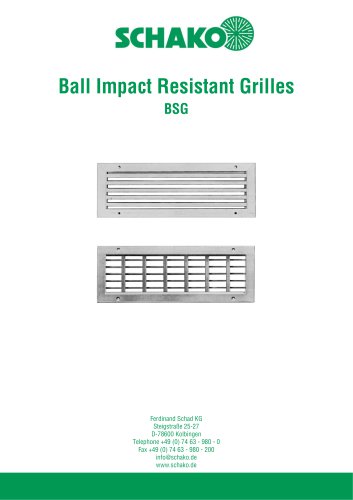 BSG
BSG19 Pages
 KG
KG19 Pages
 IB-Q
IB-Q21 Pages
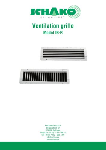 IB-R
IB-R15 Pages
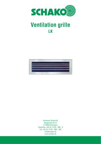 LK
LK12 Pages
 PA
PA32 Pages
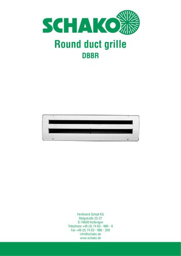 DBBR
DBBR6 Pages
 KGRR
KGRR17 Pages
 DBBRR
DBBRR11 Pages
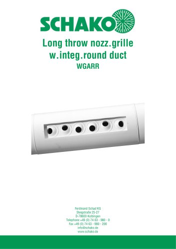 WGARR
WGARR7 Pages
 WGA
WGA29 Pages
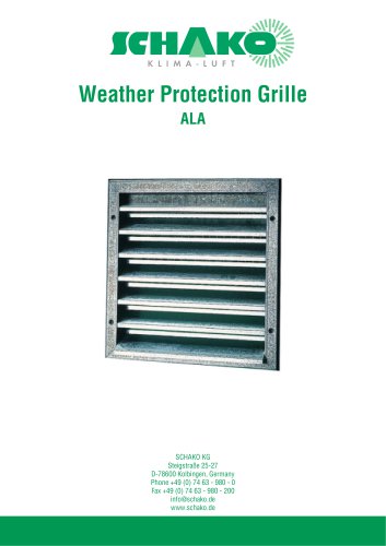 ALA
ALA4 Pages
 ALA-R
ALA-R4 Pages
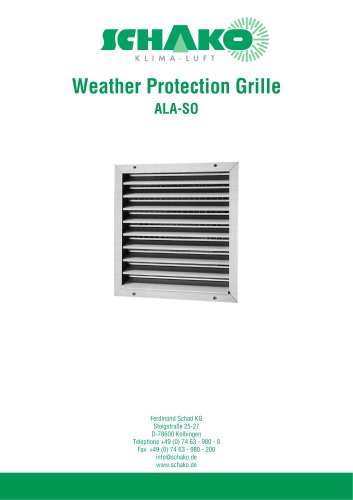 ALA-SO
4 Pages
 ALAS
ALAS10 Pages
 ALAS-P
5 Pages
 DKAPPs
6 Pages
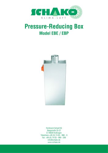 EBE/EBP
52 Pages
 DKG
DKG6 Pages
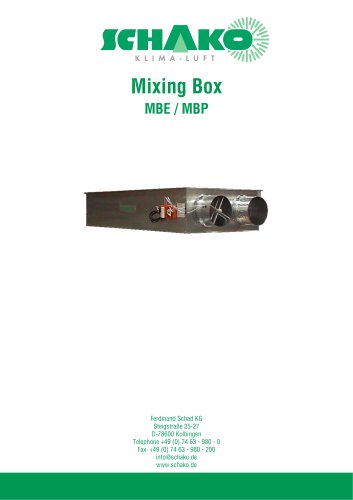 MBE/MBP
27 Pages
 PIANO
PIANO27 Pages
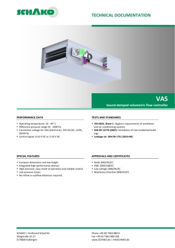 VAS
VAS26 Pages
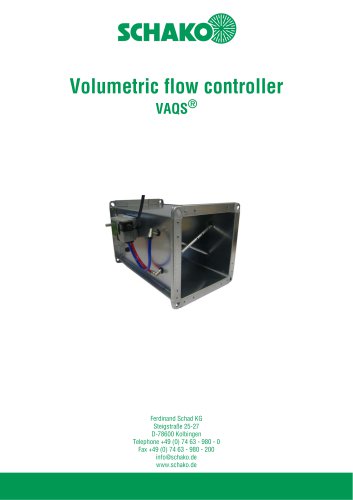 VAQS
VAQS19 Pages
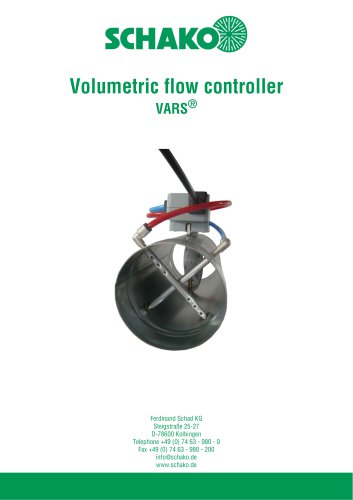 VARS
VARS26 Pages
 VRAPPs
20 Pages
 VRAR
VRAR52 Pages
 MAK
MAK15 Pages
 RS-F
RS-F7 Pages
 RS
RS15 Pages
 EasyBus
24 Pages
 DISA-Family
4 Pages
 RMS
RMS11 Pages
 TSR
TSR5 Pages
 VLV
VLV31 Pages
 MBM
MBM10 Pages
 LL
LL7 Pages
 RR-Complete
41 Pages
 MINODSX
6 Pages
 SPB
SPB10 Pages
 DISA-H
34 Pages
 AQUARIS SILENT
38 Pages
 NBS
NBS24 Pages
 JK-LP/JK-LU
15 Pages
 HKP / HKU
16 Pages
 FKW
FKW16 Pages
 FLARE
FLARE13 Pages
 RF
RF7 Pages
 KGF
KGF9 Pages
 SVA-FF
8 Pages
 BKA-Ü
BKA-Ü35 Pages
 BSK-RPR
60 Pages
 BKP-EN
40 Pages
 BAK-240
6 Pages
 BAK-250
14 Pages


- Ventilation grill
- Industrial air conditioner
- Metal ventilation grill
- Rectangular ventilation grill
- Commercial detector
- Commercial air conditioning cabinet
- Reversible air conditioner
- Aluminum ventilation grill
- Exterior ventilation grill
- Commercial ventilation grill
- Facade ventilation grill
- Ceiling-mounted air diffuser
- Industrial fan coil
- White ventilation grill
- Industrial convector
- Home ventilation grill
- Metal convector
- Contemporary convector
- Wall-mounted air conditioner