- Company
- Products
- Catalogs
- News & Trends
- Exhibitions
AQUARIS SILENT
1 /38Pages
AQUARIS SILENT
1 /38Pages
Catalog excerpts

11/01 - 2 Construction subject to change. Version: 05.04.2013 No return possible!
Open the catalog to page 2
Fan Coil Unit Aquaris Silent Description The Aquaris Silent fan coil units are air-conditioners that are especially designed for the decentralised use, for heating or cooling with circulating air. The fan coil units guide the air to be treated through the heat exchanger where it can be heated or cooled in a particularly energy-efficient way. They are used to bring the air quickly to the desired temperature and require only small heating or cooling surfaces. The optimised heat transmission allow lower supply temperatures during heating. And higher supply temperatures during cooling. This minimises...
Open the catalog to page 3
Fan Coil Unit Aquaris Silent Condensate pan The condensate pan can be mounted horizontally or vertically and serves for the collection of the condensate water below the cooling register. The pan is made of galvanised steel and has a thermal insulation (polyethylene with a thickness of 3 mm) to avoid the formation of condensation water. The condensation water outlet is located on the same side as the hydraulic connections and can be connected to the on-site drain system. Motorised fan The motorised fan consists of double-sided intake-operation, dynamically balanced centrifugal blowers with forward...
Open the catalog to page 4
Fan Coil Unit Aquaris SilentModels, dimensions and weights Dimensions and weights Base unit Housing (optional accessories) A= cold water outlet (cylindrical internal thread, EN 10226-1 Rp 1/2) B= cold water outlet (cylindrical internal thread, EN 10226-1 Rp 1/2) C= cold water outlet (cylindrical internal thread, EN 10226-1 Rp 1/2) D= cold water outlet (cylindrical internal thread, EN 10226-1 Rp 1/2) E = Condensate drain DN16 mm (external) G1 = Weight of the base unit G2 = Weight of the base unit, including device casing To avoid deposits and corrosion, the water quality for filling the registers...
Open the catalog to page 5
Fan Coil Unit Aquaris Silent Models Horizontal installation with hydraulic connection on the right -H...-R Horizontal installation with hydraulic connection on the left -H...-L Vertical installation with hydraulic connection on the right -V...-R Vertical installation with hydraulic connection on the left -V...-L Vertical model This unit was especially developed for wall mounting. Horizontal model Its compact size and low height make the Aquaris Silent fan coil unit an ideal solution for installation in false ceilings and floors, also allowing an open installation suspended from the ceiling. Unit...
Open the catalog to page 6
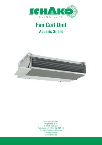
Fan Coil Unit Aquaris Silent Electric connections Electric connection diagram (SP series) Cooling valve Condensate pump Thermo contact Thermo contact Heating valve Connect the fan coil unit to the earthing cable. Interrupt the power supply, before carrying out any electrical connection work. SCHAKO cannot be held liable for faulty electrical connections or incorrectly dimensioned connecting cables. Stage 2 Stage 3 Stage 4 Stage 5 Stage 6 Condensate pump Heating valve Cooling valve Electric connection diagram (EC series) 11/01 - 7 Construction subject to change. Version: 05.04.2013 No return possible!...
Open the catalog to page 7
Fan Coil Unit Aquaris Silent Wiring thermo contact, overload protection, operational and fault message (SP series) ON-SITE Room controller Yellow Green White (*) White (*) Blue Brown Black Grey Purple Orange Red Blue Brown Yellow / Green Wiring thermo contact, overload protection, operational and fault message (EC series) ON-SITE Room controller Connection depending on the signal type Yellow / Green Brown White (*) = potential-free thermo contact as overload protection for motor, to be provided on-site 11/01 - 8 Construction subject to change. Version: 05.04.2013 No return possible!
Open the catalog to page 8
Fan Coil Unit Aquaris Silent Circuit diagram (with thermo contact) 1 speed switch + 2 or more fan coils (SP series) ON-SITE Speed switch Yellow Green Yellow Green White (*) White (*) Blue Brown Black Grey Purple Orange Red Yellow/ Green White (*) White (*) Blue Brown Black Grey Purple Orange Red Yellow/ Green White (*) = potential-free thermo contact as overload protection for motor, to be provided on-site 11/01 - 9 Construction subject to change. Version: 05.04.2013 No return possible!
Open the catalog to page 9
Fan Coil Unit Aquaris Silent Circuit diagram (with thermo contact) 1 speed switch + 2 or more fan coils (EC series) ON-SITE N L Room controller Yellow / Green Brown Connection depending on the signal type Yellow / Green Brown 11/01 - 10 Construction subject to change. Version: 05.04.2013 No return possible!
Open the catalog to page 10
Fan Coil Unit Aquaris Silent Quick selection diagrams SP series Total cooling capacity (4-pipe system) (1) (see conditions on Page °15) 8,0 7,5 7,0 6,5 Total heating capacity (4-pipe system) (1) (see conditions on Page °15) cooling and heating capacities at speed level 1-6 11/01 - 11 Construction subject to change. Version: 05.04.2013 No return possible
Open the catalog to page 11
Fan Coil Unit Aquaris Silent EC series Total heating capacity (2-pipe system) (2) Total cooling capacity (2-pipe system) (2) Total cooling capacity (4-pipe system) (2) (see conditions on Page °16) Total heating capacity (4-pipe system) (2) (see conditions on Page °16) (2) cooling and heating capacities at 1-10V Construction subject to change.
Open the catalog to page 12
ICHAKO Fan Coil Unit Aquaris Silent Technical data Nominal capacity 2-pipe systems SP series Calculations with filter G2 (1) Measured at 0 Pa of available pressure (2) Air inlet temperature = 27°C, water inlet temperature = 7°C, temperature difference = 5°C (3) Air inlet temperature = 20°C, water inlet temperature= 50°C, same water throughput as in cooling (2)
Open the catalog to page 13
Fan Coil Unit Aquaris SilentEC series Calculations with filter G2 (1) Measured at 0 Pa of available pressure (2) Air inlet temperature = 27°C, water inlet temperature = 7°C, temperature difference = 5°C (3) Air intake temperature = 20°C, water intake temperature= 50°C, same water throughput as in cooling (2) Version: 05.04.2013 Construction subject to change. No return possible!
Open the catalog to page 14All SCHAKO KG catalogs and technical brochures
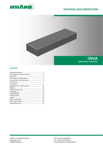 CNVA
CNVA32 Pages
 FKW (2025)
28 Pages
 KGF Compact Filter Grille
9 Pages
 AUDIX
AUDIX2 Pages
 DISA
DISA4 Pages
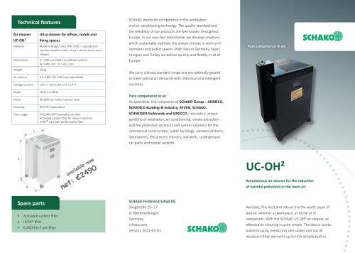 UC-OH²
2 Pages
 IGA
IGA2 Pages
 CDD
CDD2 Pages
 FBS
FBS18 Pages
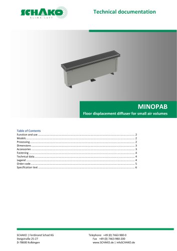 MINOPAB (2025)
6 Pages
 PIL
PIL23 Pages
 MWS / MWK
23 Pages
 ERK-SO
43 Pages
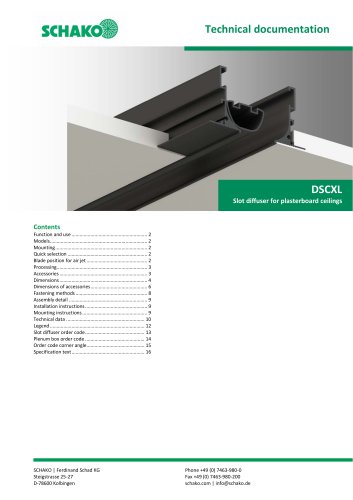 DSCXL
DSCXL17 Pages
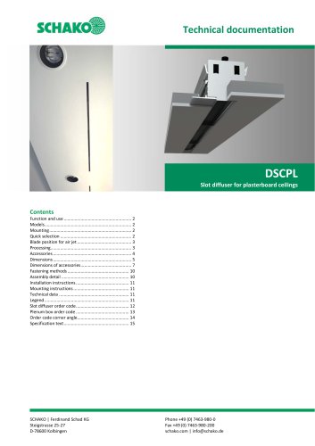 DSCPL
DSCPL16 Pages
 BKSYS
BKSYS18 Pages
 MINODSA
6 Pages
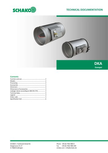 DKA
DKA6 Pages
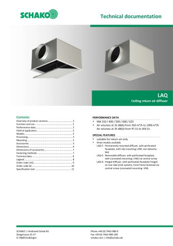 LAQ
LAQ11 Pages
 VMPR/VMPQ
29 Pages
 DSCU
DSCU18 Pages
 DSCP
DSCP15 Pages
 DQJP
DQJP9 Pages
 BKA-EN
79 Pages
 CPL
CPL15 Pages
 AUDIX®
25 Pages
 VREX
VREX26 Pages
 VQEX
VQEX17 Pages
 VPEX
VPEX18 Pages
 SVA-FS
11 Pages
 NRWG
NRWG22 Pages
 COMBIDSC
26 Pages
 DSC
DSC37 Pages
 DO
DO10 Pages
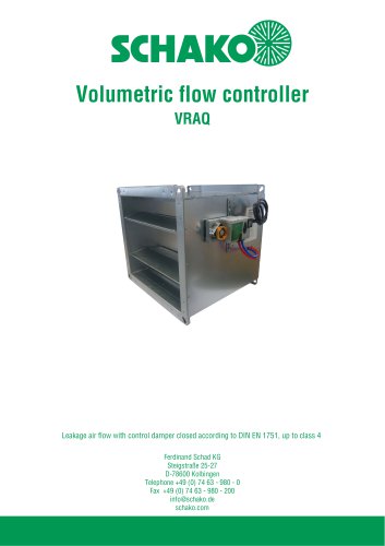 VRAQ
VRAQ46 Pages
 UEKU
UEKU6 Pages
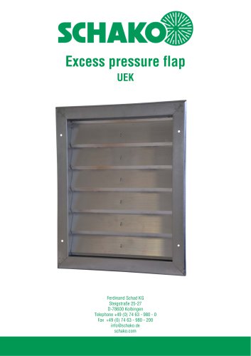 UEK
UEK6 Pages
 SS-K
SS-K6 Pages
 VOLKOM
6 Pages
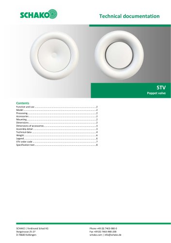 STV
STV8 Pages
 DQJ
DQJ38 Pages
 ALAS-F 125
6 Pages
 ALPETY
16 Pages
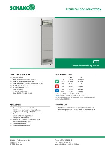 CTT
CTT23 Pages
 KWB
KWB19 Pages
 GREENKIT
20 Pages
 SVA-FF
15 Pages
 FKU
FKU31 Pages
 FKF
FKF29 Pages
 SGA
SGA5 Pages
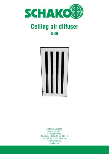 DBB
DBB27 Pages
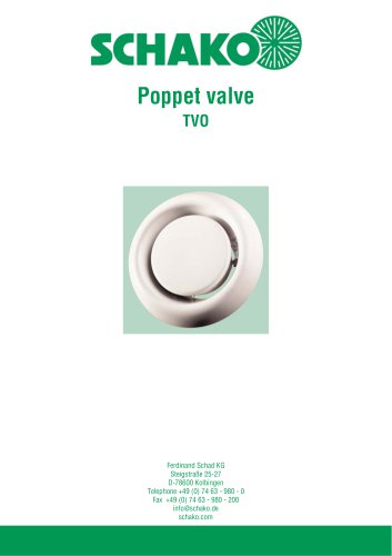 TVO
TVO8 Pages
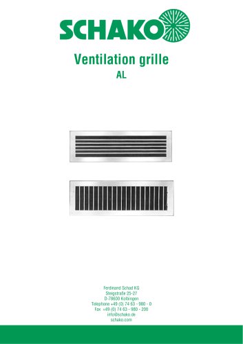 AL
AL23 Pages
 RF Return air filter grille
7 Pages
 NBS
NBS34 Pages
 MKAR_MKAQ
13 Pages
 KF
KF4 Pages
 JK
JK16 Pages
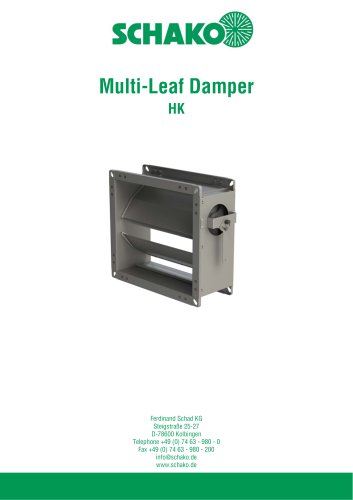 HK
HK16 Pages
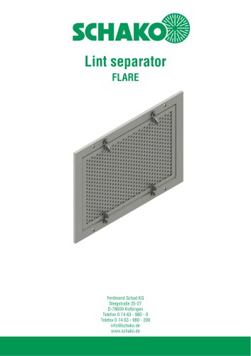 Lint Separator FLARE
13 Pages
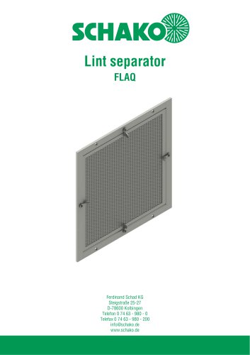 FLAQ
FLAQ11 Pages
 FG
FG14 Pages
 ERK-MB
38 Pages
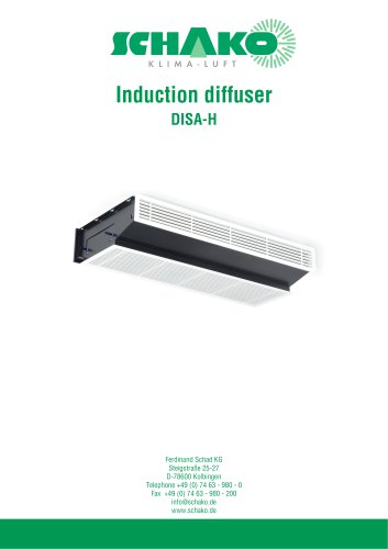
 DISA-H (2025)
34 Pages
 DISA-360
32 Pages
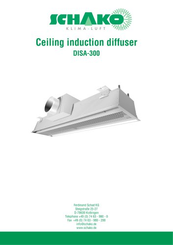 DISA-300
51 Pages
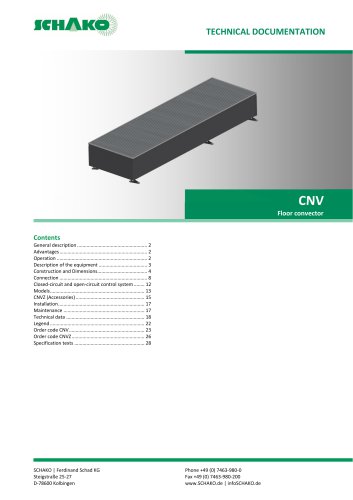 CNV
CNV29 Pages
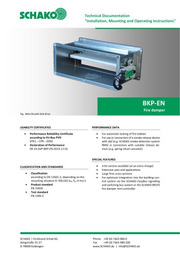
 BKP-EN Fire damper
40 Pages
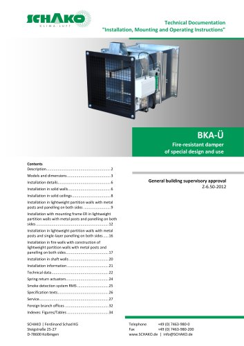 BKA-UE
35 Pages
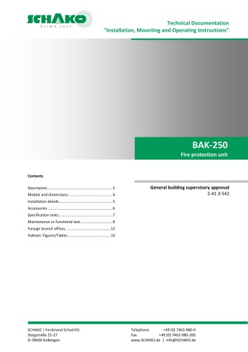
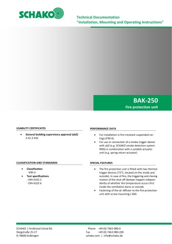 BAK-250 Fire protection unit
17 Pages
 BAK-240
16 Pages
 Aquaris-Silent
38 Pages
 Aquaris_KWB
20 Pages
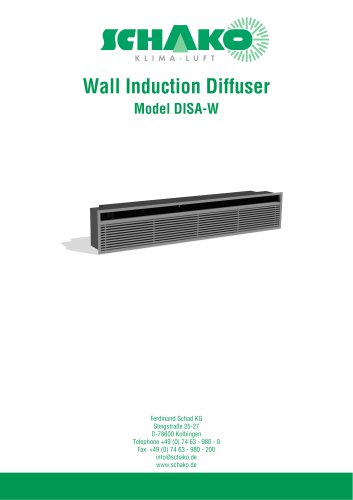 DISA-W
43 Pages
 CULTRA-Studioline
24 Pages
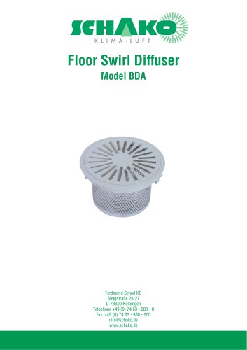 BDA
BDA11 Pages
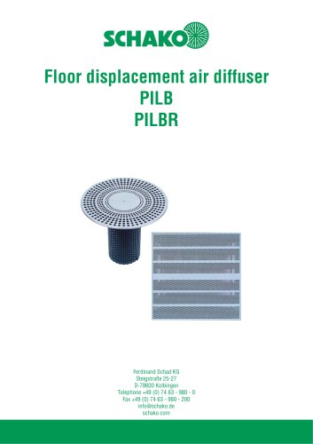 PILB/PILBR
33 Pages
 DAV
DAV19 Pages
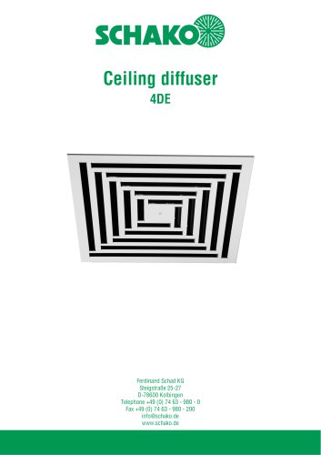 4DE
4DE18 Pages
 4DF
4DF13 Pages
 DQC
DQC16 Pages
 DQDL
DQDL16 Pages
 IDA
IDA21 Pages
 IKA
IKA23 Pages
 ZMD
ZMD17 Pages
 DQF
DQF15 Pages
 DQJF
DQJF12 Pages
 DQJA/DQJR
10 Pages
 DQJSL
DQJSL17 Pages
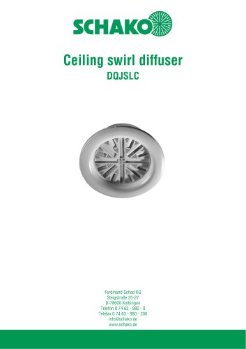 DQJSLC
17 Pages
 DHV
DHV18 Pages
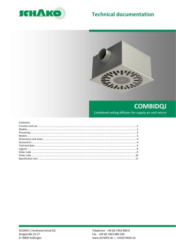 COMBIDQJ
11 Pages
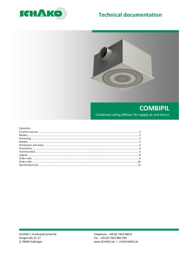 COMBIPIL
11 Pages
 DSA
DSA15 Pages
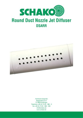 DSARR
DSARR7 Pages
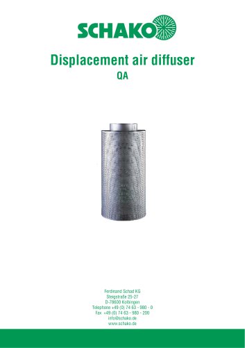 QA
QA30 Pages
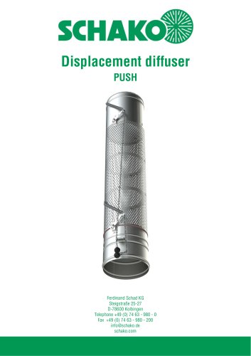 PUSH
PUSH23 Pages
 WQA
WQA12 Pages
 DSX
DSX25 Pages
 DSX-XXL
23 Pages
 AUDIX®-AW
20 Pages
 AUDIX®-ÜSG
13 Pages
 DSX-XXL-W
25 Pages
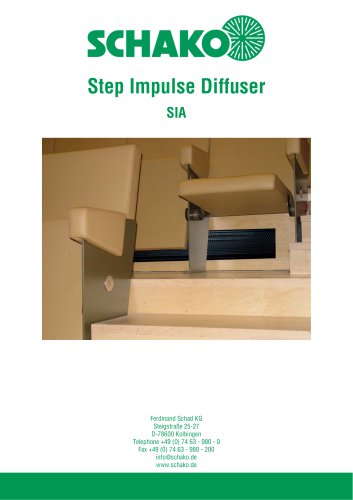 SIA
SIA7 Pages
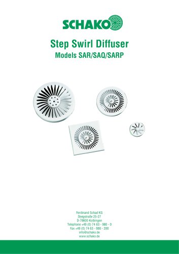 SAR/SAQ/SARP
13 Pages
 WDA
WDA32 Pages
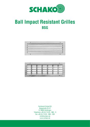 BSG
BSG19 Pages
 KG
KG19 Pages
 IB-Q
IB-Q21 Pages
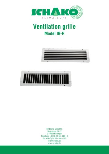 IB-R
IB-R15 Pages
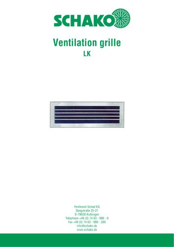 LK
LK12 Pages
 PA
PA32 Pages
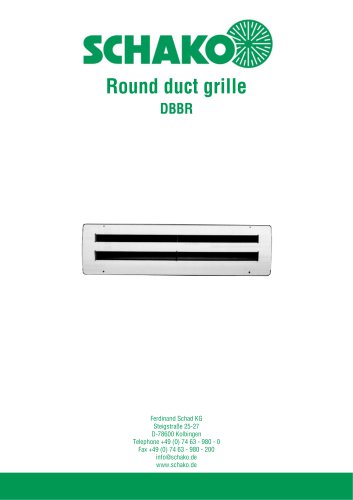 DBBR
DBBR6 Pages
 KGRR
KGRR17 Pages
 DBBRR
DBBRR11 Pages
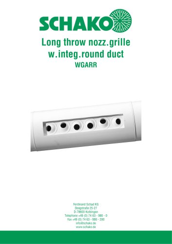 WGARR
WGARR7 Pages
 WGA
WGA29 Pages
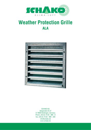 ALA
ALA4 Pages
 ALA-R
ALA-R4 Pages
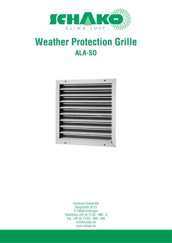 ALA-SO
4 Pages
 ALAS
ALAS10 Pages
 ALAS-P
5 Pages
 DKAPPs
6 Pages
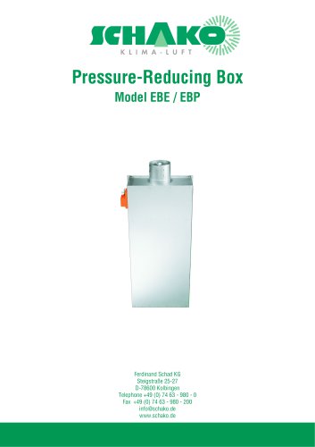 EBE/EBP
52 Pages
 DKG
DKG6 Pages
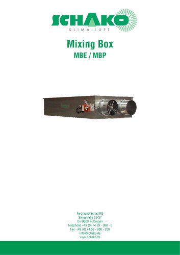 MBE/MBP
27 Pages
 PIANO
PIANO27 Pages
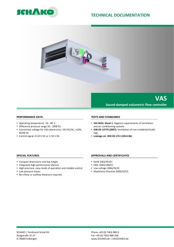 VAS
VAS26 Pages
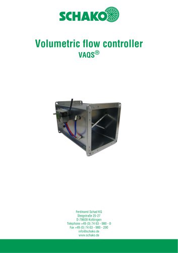 VAQS
VAQS19 Pages
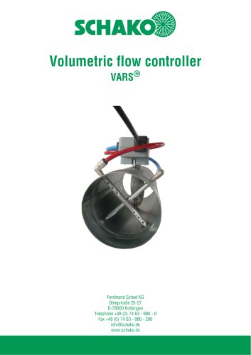 VARS
VARS26 Pages
 VRAPPs
20 Pages
 VRAR
VRAR52 Pages
 MAK
MAK15 Pages
 RS-F
RS-F7 Pages
 RS
RS15 Pages
 EasyBus
24 Pages
 DISA-Family
4 Pages
 RMS
RMS11 Pages
 TSR
TSR5 Pages
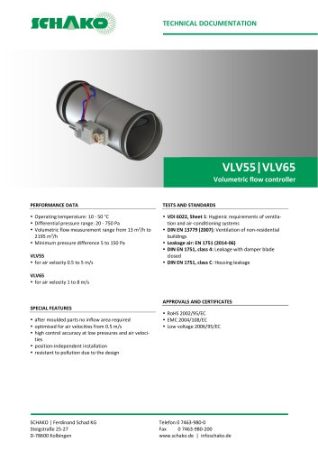 VLV
VLV31 Pages
 MBM
MBM10 Pages
 LL
LL7 Pages
 RR-Complete
41 Pages
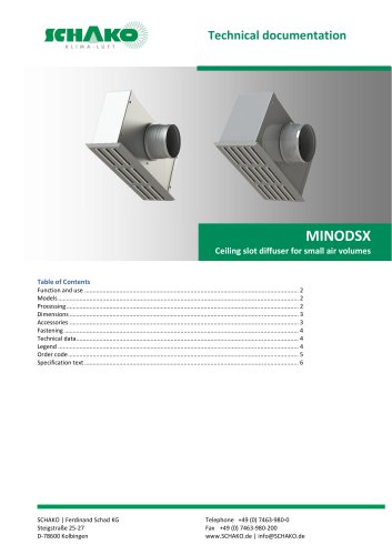 MINODSX
6 Pages
 SPB
SPB10 Pages
 DISA-H
34 Pages
 NBS
NBS24 Pages
 JK-LP/JK-LU
15 Pages
 HKP / HKU
16 Pages
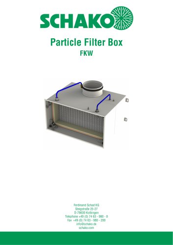
 FKW
FKW16 Pages
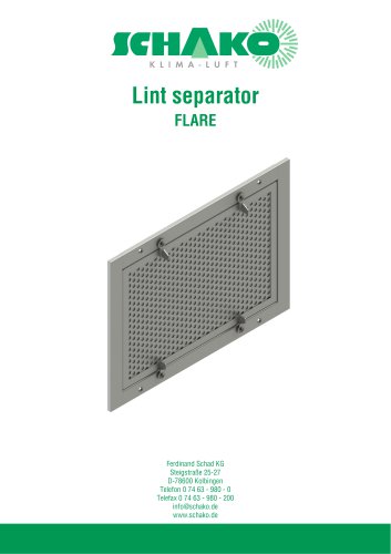 FLARE
FLARE13 Pages
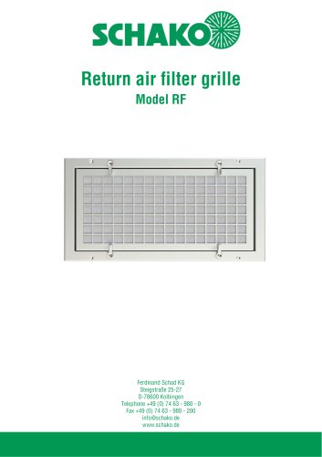 RF
RF7 Pages
 KGF
KGF9 Pages
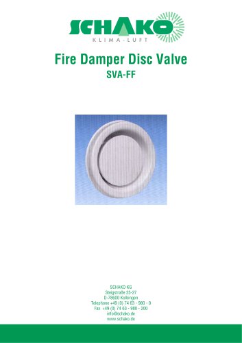 SVA-FF
8 Pages
 BKA-Ü
BKA-Ü35 Pages
 BSK-RPR
60 Pages
 BKP-EN
40 Pages
 BAK-240
6 Pages
 BAK-250
14 Pages


- Ventilation grill
- Industrial air conditioner
- Metal ventilation grill
- Rectangular ventilation grill
- Commercial detector
- Commercial air conditioning cabinet
- Industrial air diffuser
- Reversible air conditioner
- Aluminum ventilation grill
- Exterior ventilation grill
- Commercial ventilation grill
- Facade ventilation grill
- Ceiling-mounted air diffuser
- White ventilation grill
- Industrial convector
- Home ventilation grill
- Metal convector
- Contemporary convector
- Wall-mounted air conditioner