


- Company
- Products
- Catalogs
- News & Trends
- Exhibitions
Wall Cream

Wall Cream
- Pulleys: Use maximum diameter pulleys to enhance teeth engagement and belt speed. Zero backlash pulleys are recommended for precision. Ensure high-quality pulleys.
- Minimum Pulley Diameter: Depends on belt construction, load, and drive configuration. Consult ELATECH® for smaller pulleys.
- Clamping Plates: Must match belt profile, be rigid, and provide uniform force. Minimum 7 teeth in clamp; 12 for HPL cords.
- Machine Structure: Ensure rigidity for reliable drive and repeatability.
- Angular Drives: For "Twisted" drives, maintain span length > 20 times belt width for 90° twist.
- Omega Drive: Maintain span length > 3 times belt width between driver pulleys and idlers.
- Belt Life: Follow technical specifications for pulley geometry and belt storage to achieve 3 million reverse bending cycles over 10 years.
- Drive Installation: Ensure belt teeth and pulley grooves match before tensioning.
- Breaking Load: Dependent on alignment and clamping. Use safety factors and consult ELATECH® for guaranteed loads.
- Belt Drive Tension: Correct tension and alignment optimize belt life and reduce noise.
- Drive Alignment: Misalignment causes unequal tension and noise. Use straight edge or laser tool for alignment.
- Idlers: Use toothed idlers on slack side. Avoid flat idlers to prevent noise and wear.
- Store belts in protective containers, away from sunlight, chemicals, and ozone sources. Handle with care to avoid damage.
- Online tool for efficient drive calculation, always up-to-date, covering power transmission, linear, and transport applications.
- Includes definitions for terms like torque, angular velocity, and safety factors. Provides formulas for calculating forces, tension, and elongation.
- Ensure total peripheral force satisfies tooth shear strength, tensile load, and flexibility. Consider mass, transmission cycle, and friction forces.
- Use large diameter pulleys to optimize performance. Calculate total mass and necessary forces.
- Verify belt width, installation pretension, allowable tensile load, and flexibility.
- Calculate shaft load and static elongation for linear and "Omega" drives.
- Determine positioning accuracy based on stiffness coefficient.
- AT5 Timing Pulleys: The document lists measurements for z ranging from 87 to 120, with corresponding da and dw values.
- AT10 Timing Pulleys: Measurements are provided for z ranging from 15 to 120, with detailed da and dw values.
- ATF10 Timing Pulleys: Similar to AT10, with measurements for z ranging from 15 to 120.
- SAT10 Timing Pulleys: Includes data for z ranging from 18 to 120.
- AT20 Timing Pulleys: Specifications for z ranging from 18 to 120 are included.
- ATF20 Timing Pulleys: Data is provided for z ranging from 18 to 120.
- ATL5 Timing Pulleys: Measurements for z ranging from 25 to 120 are detailed.
- ATL10 Timing Pulleys: Includes specifications for z ranging from 25 to 120.
- ATL20 Timing Pulleys: Data for z ranging from 12 to 29 is provided.
- The document provides a comprehensive list of diameters for each pulley type, which are critical for selecting the appropriate pulley for specific applications.
- The measurements are given in millimeters, ensuring precision in design and application.
- HTD14M: Covers a range of teeth from 34 to 120, with da and dw measurements increasing incrementally.
- RPD5M: Includes teeth from 18 to 120, with specific da and dw values provided for each tooth count.
- RPD8M: Similar structure to RPD5M, with measurements for teeth ranging from 32 to 120.
- STD5M: Lists teeth from 18 to 120, with detailed da and dw values.
- STD8M: Provides measurements for teeth from 32 to 120.
Catalog excerpts

Drive calculation GUIDELINES Pulleys It is recommended to use pulleys with the maximum diameter allowed by the application in order to maximise the number of teeth in mesh and increase the belt peripheral speed. For applications where high positioning precision is required, it might be useful to use zero backlash pulleys. In order to guarantee a reliable drive, it is recommended to use superior quality pulleys. Minimum pulley diameter Minimum pulley diameter depends on belt construction but also on the load and the configuration of the drive. The values reported in the catalogue have been calculated...
Open the catalog to page 2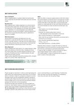
BELT INSTALLATIONDrive installation When installing belts on pulleys, before tensioning the drive, check that the belt teeth and pulley grooves correctly match. Belt breaking load is highly dependent on several factors including pulley alignment, clamping system and others. The data given in the catalogue are average values tested in our laboratory. It is recommended to use adequate safety factors and ask the ELATECH® technical department for minimum guaranteed breaking load in applications where it is needed. Correct belt drive tension and alignment are very important to optimize belt life and...
Open the catalog to page 3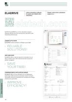
online calculation software for quick and reliable drive calculation Elatech online drive calculation support at ↓ ELATECH’s ELADRIVE is a drive calculation program allowing efficient and time saving drive calculation with improved performances. ALWAYS UP TO DATE ELADRIVE online version is always up to date. › RELIABLE SOLUTIONS! FAST AND EASY ELADRIVE offers a step by step drive calculation by an easy to follow menu with improved screen layouts for quicker navigation. › SAVE YOUR TIME! COMPREHENSIVE APPLICATION RANGE Drive Calculation ELADRIVE offers a drive calculation for all application technology...
Open the catalog to page 4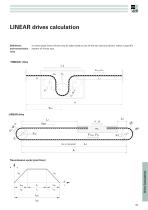
LINEAR drives calculation Definitions and transmission cycle In most cases linear drives may be taken back to one of the two layouts shown, where a specific system of forces acts. “OMEGA” drive v, a FTzul, FTv mc LINEAR drive A Transmission cycle (rpm/time) v ab Drive Calculation
Open the catalog to page 5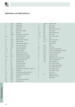
[cm] Belt minimum width [N/mm] Belt modulus / spring rate [N] Specific spring rate [mm] Effective centre distance [mm] Outside pulley diameter [mm] Pitch circle diameter [mm] Idler pulley diameter [N] Dynamic shaft load [N] Static shaft load [N] Maximum span force [N] Resisting force of friction [N/cm] Specific tooth shear strength [N] Pretension force for belt side [N] Allowable tensile load [N] Vertical lifting force [mm] Difference of position due to force [mm] Length of tight and slack side [Nm] Torque during acceleration Specific weight Total mass Mass of carriage / slide Pulley mass Pulley...
Open the catalog to page 6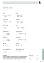
Torque Power M _ Fu 'd w _ P' 9550 2000 n M • n FU • v 9550 _ 1000 Peripheral force Linear speed Fu = 60000•v z • t Acceleration time Acceleration travel tab Braking time Braking travel ‘av _ i _ Total travel Sges _ Sab + Sc + Sav Time at constant speed Travel at constant speedsc = v • tc • 1000 v • 1000 Safety factor ELATECH® belts do not need any safety factor. However if there are unknown peaks or shock loads or swings in the peripheral force unknown at design time, which therefore can not be included in the calculation parameters, a suitable safety factor should be considered by the designer....
Open the catalog to page 7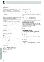
Calculation Linear drives are correctly dimensioned when the total peripheral force, necessary for the requested work, satises the 3 technical parameters of the selected belt: ∙ tooth shear strength ∙ allowable tensile load ∙ exibility Determine the belt width with FUspez depending on the rpm of the small pulley (see technical data on tooth shear strength for the selected belt type). The necessary data for the calculation are: the mass to be moved, the transmission cycle, the drive layout with the related forces, the resisting force of friction. Friction force is generally determined by the linear...
Open the catalog to page 8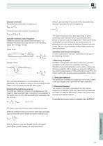
Calculate shaft load The shaft load under static conditions is: Being FU the resulting force on the slide, the positioning deviation generated by belt elongation is: The shaft load under dynamic conditions is: FWdyn = 2 ⋅ FTV + FU Calculate necessary static elongation Installation tension generates a belt elongation “Δl” between the shafts (for linear drives) or the clamping plates (for “Omega” drives). Linear drive L1 Fu ,M Omega” drive v, a FTzul, FTv mc If the resulting elongation is not acceptable for the application, it is possible to reduce it by increasing the belt width or by increasing...
Open the catalog to page 9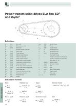
Power transmission drives ELA-flex SD® and iSync® Definitions lr [cm] Belt minimum width - Number of teeth of the belt [mm] Effective center distance [mm] Pulley bore diameter [mm] Pulley outside diameter [mm] Small pulley outside diameter [mm] Large pulley outside diameter [mm] Pulley pitch diameter [mm] Small pulley pitch circle diameter [mm] Large pulley pitch circle diameter [N] Static shafts load [N] Pretension force per belt side [N] Allowable tensile load Specific Torque Power Specific Power Acceleration time Deceleration time Peripheral speed Number of teeth of the small pulley Number...
Open the catalog to page 10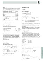
Belt selection is made according to a constant working load. For start up torque and in case of peak loads and vibrations a safety factor c1 must be considered. Calculate teeth in mesh Transmission with steady load c1 = 1,0 Transmission with peak or fluctuating loads: For speed up driver factor c2 must be considered: i = from 0,66 to 1 c2 = 1,1 The resulting total safety factor is: c0 = c1 • c2 with p [°]= wrap angle t-(z9 - zk ) Determine belt width Note: zemax = 12 for belts ELA-Flex SD® or iSync® zemax = 6 for belts ELATECH® V Drive calculation The necessary data for drive calculation are:...
Open the catalog to page 11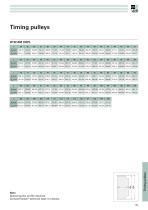
NoteSpecial pulley profile required.Contact Elatech® technical dept. for details. 183
Open the catalog to page 35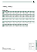
NoteSpecial pulley profile required.Contact Elatech® technical dept. for details. 187
Open the catalog to page 39All San Marco catalogs and technical brochures
 Cadoro
100 Pages
 Allover base
7 Pages
 Acrylosilox
12 Pages
 Acrylosatin plus
12 Pages
 Acrylomat plus
12 Pages
 Acrisyl decora
36 Pages
 4protection
100 Pages
 Acrisyl Light
4 Pages
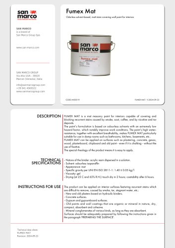 Fumex Mat
3 Pages
 Acrylosatin Plus
3 Pages
Archived catalogs
 ALLOVER
8 Pages
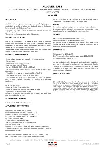 ALLOVER BASE
1 Page
 ACRYLOVELOUR PLUS
2 Pages
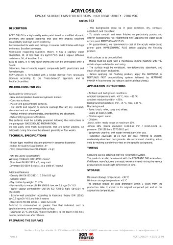 ACRYLOSILOX
2 Pages
 UNIMARC HOBBY
2 Pages
 SINTOLIN SATINATO
2 Pages
 INTERNI A COLORI
44 Pages
 ANTI-GRAFFITI SYSTEM
16 Pages
 PROFESSIONAL SYSTEMS
20 Pages
 COMPANY PROFILE
13 Pages
 Decorativi San Marco
116 Pages
- San Marco coating
- San Marco indoor paint
- San Marco decorative paint
- San Marco wall paint
- San Marco building coating
- San Marco outdoor paint
- San Marco indoor coating
- San Marco wall coating
- San Marco matte paint
- San Marco acrylic paint
- San Marco outdoor coating
- San Marco protective paint
- San Marco decorative coating
- San Marco wood paint
- San Marco water-based paint
- San Marco finish paint
- San Marco indoor primer
- Waterproofing
- San Marco metal paint
- San Marco concrete paint