 Website:
SALICE
Catalog excerpts
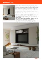
Slider M35 Top Slider M35 Top is a coplanar sliding system for medium sized cabinets, with doors width up to 1500 mm and a max. weight of 35 kg per door. The M35 Top mechanism incorporates a sophisticated magnetic damping system that decelerates the opening and closing action and sets a new standard of silent and smooth sliding movement by eliminating the typical noise produced by spring- action dampers. In its standard version, the M35 Top can be used to open two identical coplanar doors, or a single sliding door paired with a hinged door or an open compartment. In addition to the standard...
Open the catalog to page 3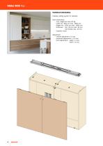
Technical information Coplanar sliding system for cabinets. Door dimensions: • max. weight per door 35 Kg • width min. 600 mm max. 1500 mm • height min. 1200 mm max. 1800 mm • thickness: - min. 18 mm max. 30 mm - with handle max. 40 mm • material: wood Adjustment: • vertical adjustment ± 5 mm • horizontal adjustment ± 3.5 mm • front adjustment: - upper ± 3 mm - lower ± 2 mm
Open the catalog to page 4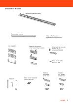
Horizontal supporting profile Transmission brackets Sliding profile for door Door adjusters Plates for the rotation of the transmission bracket Runner stop for door and activator for the transmission bracket Fixing clip for sliding profile for door Stabiliser and damper for left door Hardware Stabiliser and damper for right door Fixing clip for horizontal supporting profile
Open the catalog to page 5
Slider M35 Top - Assembly typology REGOLATORI ESTERNI REGOLATORI INCASSATI Recessed adjusters External adjusters Relation between height and width DOOR DIMENSION 1800 mm DOOR HEIGHT
Open the catalog to page 6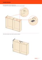
Assembly instructions Fix the fixing dowels (1) for the safety screws. Fix the clips for the horizontal supporting profile (2) with the screws provided. Check that the cabinet is level, plumb and free from distortion.
Open the catalog to page 7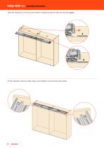
Slider M35 Top - Assembly instructions Place the mechanism to the top of the cabinet, making sure that the clips are securely engaged. Fix the mechanism with the safety screws, pre-installed in the previously fixed dowels.
Open the catalog to page 8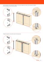
Insert the plates for the transmission rotation (1) in the pins installed at the ends of the transmission brackets. Fix to the cabinet (2) with the screws provided. Repeat the operation on the other side of the central panel.
Open the catalog to page 9
Slider M35 Top - Assembly instructions External adjusters Fix the adjusters with the appropriate plastic supports, locating the one with the double adjustment to the inside of the door (1). Place the upper and the lower sliding profile with the slots towards the center of the door. Fix the runner stop from the inside of the door (2). Double adjustment Recessed adjusters Fix the adjusters using the previously made slots, locating the one with the double adjustment to the inside of the door (1). Place the upper and the lower sliding profile with the slots towards the center of the door. Fix...
Open the catalog to page 10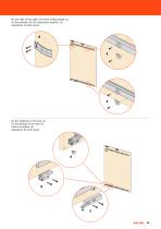
Fix the clips of the upper and lower sliding profile (1). Fix the activator for the trasmission bracket. (2). Operations for both doors. 2 Fix the stabiliser of the door (1). Fix the damper of the door (2). Place the buffers (3). Operations for both doors.
Open the catalog to page 11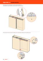
Slider M35 Top - Assembly instructions Fix the doors to the mechanism (1) with the screws provided (2). This operation must be carried out with the doors in the open position. Fully open each door and insert the wheels of the transmission brackets into the profile slots (1).
Open the catalog to page 12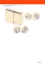
Fix on both doors the runner stop for doors (1). Fix with the screws provided (2).
Open the catalog to page 13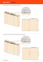
Slider M35 Top - Adjustments Open the doors and proceed with the sideways tilt adjustment. O pen the doors and proceed with the vertical adjustment using the adjusters.
Open the catalog to page 14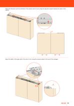
Adjust the dimension and the uniformity of the central reveal (4 mm) using the adjusters located towards the center of the cabinet. A djust the depth of the upper part of the door (3 mm) using the screws located at the end of the carriages.
Open the catalog to page 15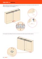
Slider M35 Top - Adjustments Adjust the depth of the lower part of the door (3 mm) loosening the fixing screws (1) and using the cam adjuster located on the plates for the rotation of the transmission brackets (2). Finally the fixing screws must be retightened. Fix the support for the stabiliser of the door on the base panel of the cabinet using the previously made slot.
Open the catalog to page 16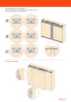
Loose the fixing screws on the stabiliser (1). Close the doors and check if the position of the stabiliser is correct. Finally the fixing screws must be retightened.
Open the catalog to page 17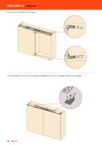
Slider M35 Top - Adjustments F ix the caps on the plates for the rotation. The closing speed of the doors can be adjusted changing the position of the springs located on the carriages.
Open the catalog to page 18
Available versions Slider M35 Coplanar sliding system for the opening of two doors Sliding system for the opening of two doors in the opposite direction Sliding system for the opening of the doors separated by a central compartment Sliding system for the opening of a single door Motorised sliding system for the opening of the doors
Open the catalog to page 19
ARTURO SALICE S.p.A. VIA PROVINCIALE NOVEDRATESE, 10 22060 NOVEDRATE (COMO) ITALIA TEL. 031 790424 FAX 031 791508 info.salice@salice.com www.salice.com DEUTSCHE SALICE GMBH RUDOLF DIESEL STR. 10 POSTFACH 1154 74382 NECKARWESTHEIM TEL. 07133 9807-0 FAX. 07133 9807-16 info.salice@deutschesalice.de www.deutschesalice.de DEUTSCHE SALICE GMBH VERKAUFSBURO NORD RINGSTRASSE 36/A30 CENTER 32584 LOHNE TEL. 05731 15608-0 FAX. 05731 15608-10 vknord@deutschesalice.de www.deutschesalice.de SALICE FRANCE S.A.R.L. ROUTE DE GOA ZAC LES 3 MOULINS 06600 ANTIBES TEL. 0493 330069 FAX. 0493 330141...
Open the catalog to page 20All SALICE catalogs and technical brochures
-
PROGRESSA
76 Pages
-
Conecta
28 Pages
-
EXCESSORIES NIGHT COLLECTION
59 Pages
-
PIN
19 Pages
-
Exedra
32 Pages
-
GLOW+
32 Pages
-
Mover - Mover Flat
36 Pages
-
Pacta - Technical pamphlet
24 Pages
-
SALICE Wind
24 Pages
-
EVOLIFT
72 Pages
-
SALICE Split
24 Pages
-
SPLIT
11 Pages
-
Lapis - Technical pamphlet
20 Pages
-
Silentia+
76 Pages
-
Universal hinges
20 Pages
-
Air
16 Pages
-
Exedra2
16 Pages
-
Smove
28 Pages
-
Slider L70 - Slider L100
24 Pages
-
Pacta - Presentation
9 Pages
-
UNICA
28 Pages
-
LINEABOX - Technical pamphlet
84 Pages
-
LINEABOX
31 Pages
-
Lapis - Presentation
13 Pages
-
Slider M35- Slider M50
24 Pages
-
Slider Glow+
2 Pages
-
NIGHT COLLECTION finishes
2 Pages
-
PACTA
9 Pages
-
WIND
15 Pages
-
Futura Push synchroniser
12 Pages
-
Futura
60 Pages
-
Vetro
16 Pages
-
AIR
13 Pages
-
Salice SHELF
16 Pages
-
SALICE PUSH
58 Pages
-
Salice SLIDER
32 Pages


