 Website:
SALICE
Catalog excerpts
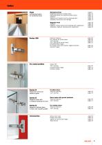
For metal profiles Mechanical Push page 6 Retaining catches for wooden doors page 10 Retaining catches for aluminium-frame doors page 11 Spacers and insertion tool for retaining catch page 13 Assembly instructions and drillings page 14 Magnetic Push page 18 Magnetic release device and retaining catch application page 20 Adjustable magnetic retaining catch application page 23 Technical features page 26 94° opening for thicker doors page 28 155° opening for thicker doors page 32 Complementary hinges: for wooden doors with positive angled assembly page 34 crampon hinges page 36 Series 200 105°...
Open the catalog to page 3
Mechanical Push
Open the catalog to page 5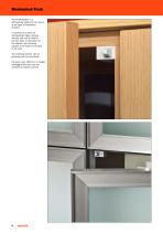
The PUSH-System is a self-opening system for the doors of all types of handleless furniture. It consists of a series of self-opening hinges, release devices that can be fitted to the top, base or side panel of the cabinet, and retaining catches to be fitted to the back of the door. The retaining catches can be pressure-fixed or screw-fixed. For doors over 1600 mm in height, we suggest that you use two mechanical release catches.
Open the catalog to page 6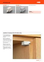
With assembly stop device. Installation of mechanical Push with adhesive strip For correct application and to ensure optimal endurance, please follow the following procedure: 1) clean and degrease the cabinet surface where the release device is to be installed using an acetone based cleaner; 2) remove the protective strip from the adhesive; 3) place the release device in position and apply a firm pressure for about one minute; 4) allow a period of 12 hours to elapse before subjecting the PUSH-System to continuous usage.
Open the catalog to page 7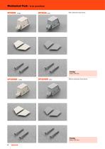
Mechanical Push DP3SNB - beige With assembly stop device. Without assembly stop device.
Open the catalog to page 8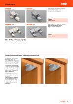
With adjustment Single adapter with depth and sideways adjustment and release device. Without assembly stop device. Double adapter with depth and sideways adjustment and release devices. Without assembly stop device. N.B.: Drilling patterns at page 14. Technical information on the adjustable mechanical Push The adjustable Push consists of a release device and a screw-fixed adapter which have been developed to improve the locating action of the system. The adjustable Push now has a depth adjustment facility with a range of -1 mm to + 2.5 mm which is controlled by a small adjuster wheel...
Open the catalog to page 9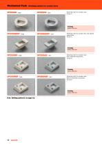
Mechanical Push - Retaining catches for wooden doors Retaining catch for wooden door. Knock-in. Retaining catch for wooden door and special assemblies. Knock-in. Retaining catch for wooden door. With assembly stop device. Screw-on. Retaining catch for wooden door. Without assembly stop device. Screw-on. N.B.: Drilling patterns at page 15.
Open the catalog to page 10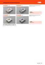
Retaining catches for aluminium-frame doors Retaining catch for aluminium-frame door width = 35 - 45 mm. Retaining catch for aluminium-frame door width = 17 - 35 mm. N.B.: Drilling patterns at pages 16
Open the catalog to page 11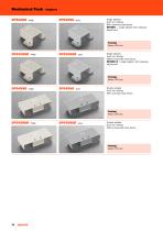
Mechanical Push - Adapters DP52SNB - beige Single adapter. 6x40 mm drilling. With assembly stop device. DP53SN_ = single adapter with sideways adjustment. Single adapter. 6x40 mm drilling. Without assembly stop device. DP53SN_R = single adapter with sideways adjustment. Double adapter. 6x16 mm drilling. With assembly stop device. Double adapter. 6x16 mm drilling. Without assembly stop device.
Open the catalog to page 12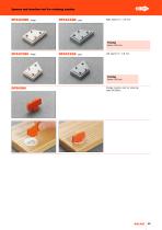
Spacers and insertion tool for retaining catches Orange insertion tool for retaining catch DP29SN_.
Open the catalog to page 13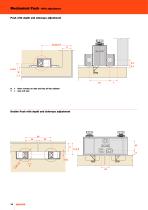
Mechanical Push - With adjustment Push with depth and sideways adjustment D = Door overlay on side and top of the cabinet Y = min. 8.5 mm Double Push with depth and sideways adjustment
Open the catalog to page 14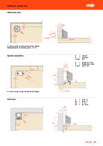
Fulloverlay door D = Door overlay on side and top of the cabinet Drilling distance of retaining catch = D + 8 D = Door overlay on side and top of the cabinet Inset door
Open the catalog to page 15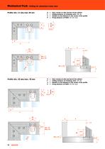
Mechanical Push - Drilling for aluminium frame door Door overlay on side and top of the cabinet Drilling distance of retaining catch = D + 8 Relative to the distance to the corner of the profile Fixing distance of PUSH = X - D + 1.3 Door overlay on side and top of the cabinet Drilling distance of retaining catch = D + 8 Relative to the distance to the corner of the profile Fixing distance of PUSH = X - D + 1.3
Open the catalog to page 16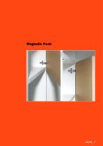
Magnetic Push
Open the catalog to page 17
Magnetic Push DPMSNB - Magnetic release devices and retaining catches Release device. ø 10 mm, 40 mm length. Packing Boxes 250 pcs. Cartons 1.500 pcs. Optional supplementary release device to increase the magnetic holding strength. It must always be used together with the DPM. The suggested position of the DPM is the point of pressure on the door. The DPA can be positioned at any point along the opening edge of the door. ø 10 mm, 40 mm length. Packing Boxes 250 pcs. Cartons 1.500 pcs. Retaining catch to be inserted. ø 11.5 mm. Retaining catch with adhesive. 20x14 mm. Adjustable magnetic...
Open the catalog to page 18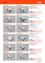
Plastic adapter for release device. To be fixed with wood screws. 7.5x32 mm drilling. Without assembly stop devices. DP81SN_R = To be fixed with Euroscrews. Packing Boxes 500 pcs. Pallets 12.000 pcs. Plastic adapter for release device. To be fixed with wood screws. 7.5x32 mm drilling. With assembly stop devices. DP81SN_ = To be fixed with Euroscrews. Packing Boxes 500 pcs. Pallets 12.000 pcs. Adjustable longitudinal plastic adapter for release device. To be fixed with wood screws. 8+16 mm drilling. Without assembly stop devices. Caps to be ordered separately. Packing Boxes 500 pcs. Pallets...
Open the catalog to page 19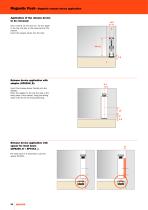
Magnetic Push - Magnetic release device application Application of the release device to be recessed Drill a hole 0 10 mm and min. 40 mm depth in the top, the side or the base panel of the cabinet. Insert the release device into the hole. Release device application with adapter (DP82SN_R). Insert the release device frontally into the adapter. Place the adapter to the top, the side or the base panel of the cabinet, using the drilling value of 8+16 mm for final positioning. Release device application with spacer for inset doors (DP82SN_R + SP44XX_). For inset doors it is essential to use the...
Open the catalog to page 20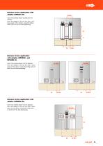
Insert the release device frontally into the adapter. Place the adapter to the top, the side or the base panel of the cabinet, using the drilling value of 8+32 mm for final positioning. 26 8 Min. Release device application with adapter (DP80SN_ and DP84SN_R). Insert the release device into the adapter. Place the adapter to the top, the side or base panel of the cabinet, using the drilling value of 8x32 mm for final positioning. Release device application with adapter (DP85SN_R). Insert the release device into the adapter. Place the adapter to the top, the side or base panel of the cabinet,...
Open the catalog to page 21All SALICE catalogs and technical brochures
-
PROGRESSA
76 Pages
-
Conecta
28 Pages
-
EXCESSORIES NIGHT COLLECTION
59 Pages
-
PIN
19 Pages
-
Exedra
32 Pages
-
GLOW+
32 Pages
-
Mover - Mover Flat
36 Pages
-
Pacta - Technical pamphlet
24 Pages
-
SALICE Wind
24 Pages
-
EVOLIFT
72 Pages
-
SALICE Split
24 Pages
-
SPLIT
11 Pages
-
Lapis - Technical pamphlet
20 Pages
-
Silentia+
76 Pages
-
Universal hinges
20 Pages
-
Air
16 Pages
-
Exedra2
16 Pages
-
Smove
28 Pages
-
Slider L70 - Slider L100
24 Pages
-
Pacta - Presentation
9 Pages
-
UNICA
28 Pages
-
LINEABOX - Technical pamphlet
84 Pages
-
LINEABOX
31 Pages
-
Lapis - Presentation
13 Pages
-
Slider M35 Top
20 Pages
-
Slider M35- Slider M50
24 Pages
-
Slider Glow+
2 Pages
-
NIGHT COLLECTION finishes
2 Pages
-
PACTA
9 Pages
-
WIND
15 Pages
-
Futura Push synchroniser
12 Pages
-
Futura
60 Pages
-
Vetro
16 Pages
-
AIR
13 Pages
-
Salice SHELF
16 Pages
-
Salice SLIDER
32 Pages


