- Catalogs
- ROTHO BLAAS
- SPIDER-en-technical-data-sheet
- Company
- Products
- Catalogs
- News & Trends
- Exhibitions
SPIDER-en-technical-data-sheet
1 /15Pages

SPIDER-en-technical-data-sheet
1 /15Pages
Catalog excerpts

CONNECTION AND REINFORCEMENT SYSTEM FOR COLUMNS AND FLOORS MULTI-STOREY BUILDINGS It allows the construction of multi-storey buildings with a column-tofloor structure. Certified, calculated and optimised for glulam, LVL, steel and reinforced concrete columns. New architectural and structural horizons. COLUMN-TO-COLUMN The steel core of the system prevents the CLT panels from being crushed and allows more than 5000 kN of vertical load to be transferred between the columns. REINFORCEMENT SYSTEM FOR CLT The arms of the system ensure the punching shear reinforcement of the CLT panels, allowing exceptional shear strength values. Column spacing greater than 7,0 x 7,0 m structural mesh. CHARACTERISTICS FOCUS multi-storey buildings STRUCTURAL MESH Rk compression greater than 5000 kN VIDEO Scan the QR Code and watch the video on our YouTube channel MATERIAL S355-S690 zinc plated steel. FIELDS OF USE Multi-storey buildings with column-to-floor system. Solid timber, glulam, high density timber, CLT, LVL, steel and concrete columns. 292 | SPIDER | PANELS AND BUILDING JOINTS
Open the catalog to page 1
WOODEN SKYCRAPERS Standard connection and reinforcement system to build wooden skyscrapers with column-to-floor system. New architectural possibilities in construction. CROSS CLT PANELS Exceptional strength and stiffness of the structure with crossed arrangement of the CLT floors. It is possible to create free spans greater than 6,0 x 6,0 m even without the use of moment joints. PANELS AND BUILDING JOINTS | SPIDER | 293
Open the catalog to page 2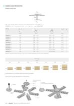
CODES AND DIMENSIONS SPIDER CONNECTOR Dtp ttp Dcyl tbp Dbp The code consists of the respective CLT panel thickness in mm (XXX = tCLT). SPI80MXXX for CLT panels with XXX = tCLT = 200 mm : code SPI80M200. CODE bottom plate SPI60S is supplied without top plate. This can be ordered separately with the code STP20020C. Also available for tCLT thickness values not shown in the table. Each code includes the following components: countersunk screw M16/M20 top plate (not included for SPI60SXXX) disc cylinder bottom plate 294 | SPIDER | PANELS AND BUILDING JOINTS
Open the catalog to page 3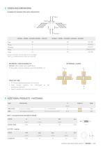
CODES AND DIMENSIONS NUMBER OF SCREWS FOR EACH CONNECTOR nco,up nbolts nincl nreinf nco,down SPI60S - SPI80S - SPI100S-SPI100L - SPI120L Screws and bolts not included in the package. The nreinf reinforcement screws are optional. EXTERNAL LOADS SPIDER: S355-S690 zinc plated steel. To be used in service classes 1 and 2 (EN 1995-1-1). FIELD OF USE • CLT floors placed precisely on columns • Solid timber, glulam, LVL softwood hardwood columns • Steel or reinforced concrete columns ADDITIONAL PRODUCTS - FASTENING type full thread connector BOLT - hexagonal head steel 8.8 EN 15048 CODE PANELS AND BUILDING...
Open the catalog to page 4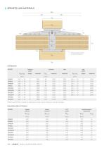
DCLT tCLT Dcyl tbp The grooving in the lower column is optional CONNECTOR MODEL cylinder material disc material SPI100L and SPI120L provide for fastening on steel columns without using the top plate. COLUMNS AND CLT PANELS MODEL upper column lower column reinforcement (optional) 296 | SPIDER | PANELS AND BUILDING JOINTS
Open the catalog to page 5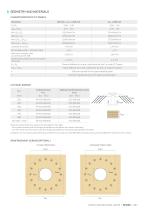
GEOMETRY AND MATERIALS CHARACTERISTICS OF CLT PANELS Parameter Lamellas thickness B/t lamellas width - thickness ratio Minimum strength class according to EN 338 Dimensional tolerance on CLT panel thickness EIx, EIy Flexural stiffness for x and y directions for the 1 m wide CLT panel Shear stiffness for x and y directions for the 1 m wide CLT panel Direction parallel to the upper lamellas grain Direction perpendicular to the upper lamellas grain CLT PANEL SCREWS tCLT inclined screws nincl optional reinforcement screws nreinf Rules for panel thickness values not included in the table: - for inclined...
Open the catalog to page 6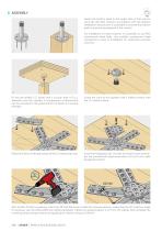
ASSEMBLY Fasten the bottom plate to the upper face of the column using the VGS Ø11 screws in accordance with the relevant installation instructions. It is possible to conceal the bottom plate in a grooving prepared in the column. For installation on steel columns it is possible to use M12 countersunk head bolts. Use suitable countersunk head connectors in case of installation on reinforced concrete columns. Fit the pre-drilled CLT panel with a circular hole of DCLT diameter onto the cylinder. A compression reinforcement can be provided to the panel bottom of beam to increase strength. Screw the...
Open the catalog to page 7
ASSEMBLY Fasten the upper plate to the lower face of the column using the VGS Ø11 screws, in accordance with the relevant installation instructions. The top plate is equipped with suitable threaded holes for fastening to the hexagonal disc. Place the upper column on the hexagonal disc and fasten it using 4 SPBOLT1235 bolts with ULS125 washer. In the case of an upper steel column, the upper plate must not be used and the column must be equipped with a suitable steel plate with holes for fastening the 4 SPBOLT1235 bolts. The slotted holes in the hexagonal disc allow the column to be rotated ±5°....
Open the catalog to page 8
For SPIDER connectors with cylinder diameter Dcyl = 100 or 120 mm, the hexagonal disc dimension is increased. In this case, the phase 6A must be replaced with phases 6B - 6F . After inserting the hexagonal disc and countersunk head screw, insert 12 HBSP8120 screws into the 12 vertical holes provided in the 6 arms. These screws will hold the arms in place in the following phases. Unscrew the countersunk head screw and remove the hexagonal disc. With a NON-PULSE screwdriver, insert the 12 VGS Ø9 screws inside the inclined washers closest to the cylinder, respecting the 45° insertion angle (if necessary...
Open the catalog to page 9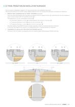
CLT PANEL PRODUCTION AND INSTALLATION TOLERANCES The connector is designed to adapt to CLT panel production and installation tolerances. The actual thickness of CLT panels may be slightly different from the nominal thickness due to a production tolerance. 1. PRODUCTION TOLERANCE ON CLT PANEL THICKNESS of ±2 mm The cone must be screwed until it touches the surface of the CLT panel (surface way to ensure contact with the cylinder (surface A ). The tolerance of ±2 mm is absorbed in the area - ), while the disc must be installed in contact between disc and arm in the area joint of 2 mm in the area...
Open the catalog to page 10All ROTHO BLAAS catalogs and technical brochures
 SHS-en-technical-data-sheet
2 Pages
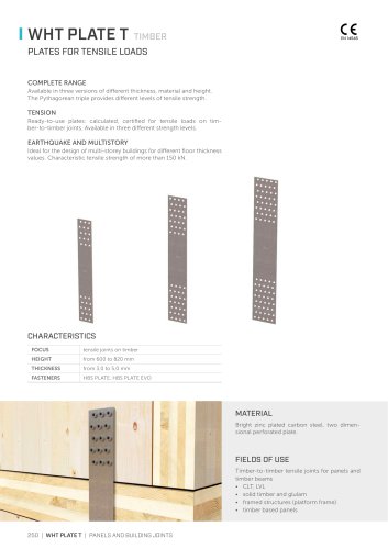 WHT PLATE T
4 Pages
 TITAN V
6 Pages
 TITAN S
13 Pages
 AIR TIGHTNESS
60 Pages
 HANDBOOK FOR TIMBER FRAME BUILDINGS
140 Pages
 Screws for wood
276 Pages
 Tools for wooden construction
178 Pages
 WOOD CONNECTORS AND TIMBER PLATES
352 Pages
 Waterproofing
180 Pages
 SOUNDPROOFING SOLUTIONS
68 Pages
 2016 FALL PROTECTION SYSTEMS
200 Pages
 structural-renovation
8 Pages
 wooden-buildings
196 Pages

Archived catalogs
 Acoustic insulation products
24 Pages
 Post Bases
28 Pages
 Terraces-and-facades
80 Pages
 2013 fall-protection
68 Pages
 rothofixing catalogue
260 Pages
- Waterproofing membrane
- Roll waterproofing membrane
- Plastic waterproofing membrane
- Roof waterproofing membrane
- Building fastening system
- Metal fastening system
- Waterproofing
- Interior fastening system
- Asphalt waterproofing membrane
- Stainless steel mounting clip
- Panel fastening system
- Industrial vapor barrier
- Polyester waterproofing membrane
- Exterior fitting fastening system
- Bituminous waterproofing membrane
- Sound-absorbing underlay
- Steel fastening system
- Foundation waterproofing membrane
- Synthetic waterproofing membrane
- Plastic vapor barrier