- Catalogs
- Rosenberg Ventilatoren
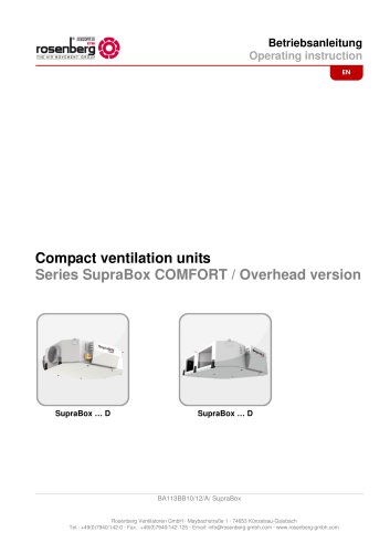
- SupraBox COMFORT 800 to 5000
SupraBox COMFORT 800 to 5000
1 /51Pages

SupraBox COMFORT 800 to 5000
1 /51Pages
Catalog excerpts
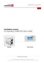
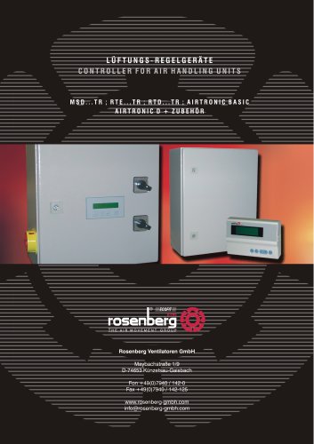
Operation Instruction |® mEcomm (O) THE AIR MOVEMENT GROUP User TerminalBA 415 AB 07/15/A/ Release 1 Rosenberg Ventilatoren GmbH ■ MaybachstraBe 1 ■ 74653 Kunzelsau-Gaisbach Tel.: +49(0)7940/142-0 ■ Fax.: +49(0)7940/142-125 ■ Email: [email protected] ■ www.rosenberg-gmbh.com
Open the catalog to page 1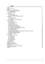
5 Normal Operation / Scope of validity 5 6.3 Scope of delivery of the Control System 8 8.8 Alarm Display, Alarm Message and Warnings 20 8.9 Unit settings, initial operation 23 8.12 Manufacturer Information, Service information and System information 26 8.13 Real value display (Status I/O) 28 9.1 Enter the service menu 33 15 Customer Service, Manufacturer's address 49
Open the catalog to page 3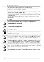
This operating manual contains important technical and safety information. Read this operating manual carefully before unpacking, mounting, commissioning and for other maintenance and service activities on the control device. It must be ensured that the operating manual is accessible and available during the operation of the ventilation unit type SupraBox COMFORT (SBC). An operator of the electronic must read the operating manual carefully and understand the information before unpacking, mounting, commissioning and for other maintenance and service activities on the control device. If there are...
Open the catalog to page 4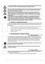
The scope of validity of this manual includes the following control versions or the assembly with the article number H42-73****: -temperature and ventilation for SupraBox COMFORT (SBC) for series 800-5000
Open the catalog to page 5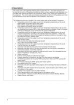
6 Description The control units or the assembly with the article number H42-73**** have been specially constructed for the control of Rosenberg Ventilatoren GmbH compact appliance series Suprabox Comfort (SBC) and represent the epitome of convenience, safety of use, control and maintenance of the equipment. The control units are produced according to the German VDE guidelines and meet the requirements of the valid EG-regulation (DIN EN 60204-1 and others). The following functions are included in the control system and can be activated if necessary: • Temperature control of the supply air and...
Open the catalog to page 6
Nominal voltage: Control voltage: Ambient temperature Operating device and IP protection type of the external operating device Wire connection from the control to the operating device Conductor Maximum power of the alarm relay IP40 for wall mounting / IP65 for front mounting Li9YY6 not crossed with RJ 11 Telephone plug, 10m cable enclosed length max.: 50m (without TCONN6J000) NYM-J 3x2,5mm2 AC 250V 10A for 1,5mm2 core cross-section The alarm relay energizes as soon as the Suprabox COMFORT (SBC) is live. In case of an alarm or the interruption of the voltage supply the relay de-energizes.
Open the catalog to page 7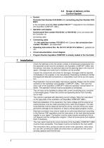
• Control: Controller Item Number H42-00400 with connecting plug Item Number H42-00401 or the complete assembly Item number H42-73**** integrated in the Ventilation Unit SupraBox COMFORT (SBC) • Operation and display: Control panel Item number H42-00104 or H42-00102, to be connected with the Controller via connecting cable • Connecting cable: 10m flat cable Item number TF5-20012 with 2 pieces tab connectors Item number TF5-20011, pre-assembled • Operating instructions Doc. No. BA 415 AA 09/14/A/ Edition 1, updated edition • Circuit documentation, circuit diagram • Program Routine SupraBox COMFORT...
Open the catalog to page 8
The collective alert contact is a changeover contact, which displays malfunctions of the equipment. The relay is energized, if there is voltage supply and no malfunction. In case of alarm message, the relay will de-energize and keep this status until the malfunction is repaired and the current alert will be acknowledged at the operating device.
Open the catalog to page 9
The integral components complete assembly Art. No. H42-73**** integrated in the ventilation unit SupraBox COMFORT (SBC) are like the labeling in the circuit documentation (circuit diagram).
Open the catalog to page 10
The Controller restarts after the supply voltage is switched on and shows the main display with the supply temperature and the plant status. If within 60s no keystroke is recognized, the display changes from every submenu automatically back to the main display. 8.1 Key Configuration
Open the catalog to page 11
Automatic operation: The automatic operation can be manually activated by pressing the [Enter] key or through the time program or with an extern switch or through an optional accessory zone operating device. This functions can be deselected in the display Menu-Overview at Settings
Open the catalog to page 13
8.3 Switch On/Off the Unit Automatic operation On and Off switching of the program routine or the control or the ventilation unit by a continuing actuation for display of the main display. Automatic operation: The automatic operation can be manually activated by pressing the [Enter] key or through the time program or with an extern switch or through an optional accessory zone operating device. This function can be deselected in the display Menu-Overview > Settings Additional information in the chapter optional accessories. # Pro9ramm lewel + Insert Password & 0000 Password request From the main...
Open the catalog to page 14
To be used to switch between the display or in the main menu, or to scroll. The possibilities to be chosen are: 1 = Settings 2 = Status I/O 3 = Time schedule 4 = Date, time 5 = System info 6 = Language 7 = Program To be used to adjust the password at the password entry level Selection of the menu group Switching in the selected input and output sides Switching to the selected program levels with the password request Password Level Service = 0077 Password Level Service and Unit configuration = 0123 The password will be reset after a selected time. Service menu after the password request Key [Up]...
Open the catalog to page 15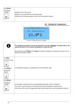
Selection of the menu group Switching in the selected input and output sides Switching to the selected program levels with the password request Set point to Menu-Overview > Settings The temperature set point can be set manually in the menu Settings. The input value is the manual set point for the comfort temperature to heat and cool. By pressing the key [Enter] while Setting is marked the display for temperature set point on the electronic controller is called. In the display changes or increase/reduce of the parameter value: In the display: Choosing of the current adjustable parameter value...
Open the catalog to page 16All Rosenberg Ventilatoren catalogs and technical brochures
 AIR CURTAINS
80 Pages
 WORLD OF AC FANS
316 Pages
 Series SupraBox COMFORT
25 Pages
 AIR CURTAINS
84 Pages
 AIRBOX air handling units
77 Pages
 EC FANGRID
2 Pages
 WORLD OF EC FANS
182 Pages
 Compact ventilation units
26 Pages
 Box fans with EC-Motor
28 Pages
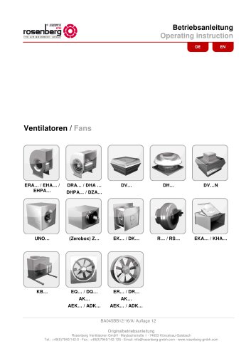 FANS
FANS23 Pages
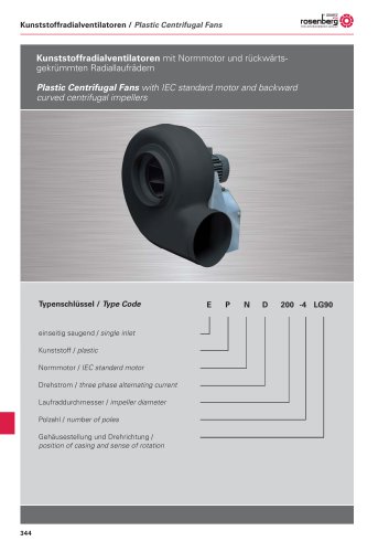 Fans made of plastic (EPND)
18 Pages
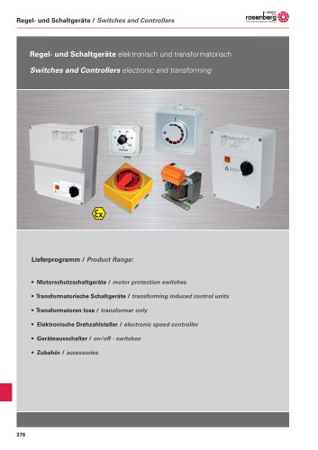 Switches and Controllers
40 Pages
 Ex fans
120 Pages
 World of fans (Standard fans)
450 Pages
 The Rosenberg Group
20 Pages
 RosenbergVentilatoren GmbH
20 Pages
 Radial Fans(Belt driven)
125 Pages
 Axial Fans for cooling
47 Pages
 EC-Radial Fans
37 Pages
 AND/B Axial Flow Fans
44 Pages
 Free Blowing fans
85 Pages
 AIR HANDLING UNITS
36 Pages
 AXIAL FLOW FANS
80 Pages
 Rosenberg Brochure
8 Pages


Archived catalogs
 WORLD OF FANS
450 Pages
- Contemporary switch
- Square switch
- Metal fan
- Commercial fan
- Indoor fan
- Mechanical ventilation unit
- White switch
- Ventilation controller
- Extractor fan
- Wall-mounted ventilation controller
- Duct fan
- Surface-mount switch
- Plastic fan
- Rocker switch
- Industrial fan
- Residential fan
- Axial fan
- Industrial centrifugal fan
- Air handling unit