- Catalogs
- Retrotouch
- INTELLIGENT DIMMER MODULE
INTELLIGENT DIMMER MODULE
1 /2Pages

INTELLIGENT DIMMER MODULE
1 /2Pages
Catalog excerpts
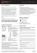
retrotouch fih&LatJ/tr<h/jic£s INTELLIGENT DIMMER MODULE. FEATURES SAFETY WARNING Before use please read carefully and use in accordance with these safety instructions. Before commencing any electrical work ensure the supply is switched OFF at the mains. Either by switching off the consumer unit or by removing the appropriate fuse. This product should be installed in accordance with the relevant sections of the building regulations code and in accordance with the latest edition of IEE regulations (BS 7671). If the unit is to be used as a replacement for an existing product, remove the existing unit from its location and disconnect the wiring. Connect the wires as shown in diagram. Ensure terminals are properly tightened and ensure no bare wires are visible. When pushing back into the backbox ensure no wires are trapped. Read the instructions carefully before starting the installation process and keep them safe for future reference. IF IN ANY DOUBT, PLEASE CONTACT A QUALIFIED ELECTRICIAN. WARNING Do not exceed the load rating as shown on the back of the product SWITCHES MUST BE INSTALLED BY A QUALIFIED ELECTRICIAN • Suitable for 1-way or2-way switching. • Minimum load down to 5W of capacitive or resistive load, such as Dimmable LED Lighting, Incandescent Lighting, MV Halogen / LV Halogen Lighting with electronic transformers. • Lamps soft-start operation, to extend longer lifetime for the lamp. • User setting for the minimum dim Level. • Build-in short circuit protect, designed to ensure the dimmer can survive in case of wiring fault or catastrophic failure of the load. • Build-in re-settable thermal cut-off to protect the dimmer over normal operation temperature caused by overloads. • Complies with BS/IEC safety standards. Operation of Dimmer Knob and Push Switch : Push knob ON or Push knob OFF the lamp. Turn knob right to increase brightness to maximum level. Turn knob left to decrease brightness to minimum level. ELECTRICAL SPECIFICATIONS NOTE: Operation at elevated temperatures or voltages may cause the thermal protection circuit to operate. If this happen, decrease the connected load to prevent re-occurance. THERMAL OVERLOAD PROTECTION Build-in thermal protect circuit. Apply a re-settable thermostat component, when module temperature raise achieve 110°C will activate the protection, while temperature cool down approx. 75°C it will become normal operation. If occur frequently, please reduce loading. SHORT CIRCUIT PROTECTION Build-in short circuit protect, once activate, the dimmer will suspend operation around 5 second after that, it will auto-ON again. If detect remain short circuit or over current, the module will suspend operation until disconnect dimmer power and Switch ON dimmer again reset to normal operation. In this case, please check the circuit with electrical technician. INSTALLATION IMPORTANT: PLEASE READ THE SAFETY WARNING BEFORE COMMENCING ANY WORK. 1. Remove the hex nut on the dimmer module, insert the shaft of the module from the rear of plate into plate cut out, fix in place using the hex nut till tight. 2. Push on the dimmer rotary knob onto the shaft until no longer loose 3. Undo the terminal screws until they no longer obstruct the cable entry holes. 4. Trim wires to correct length allow cable to reach terminals comfortably. 5. Strip back the insulation (plastic sheath) on the cable to approx 7 to 8mm. 6. Caution: An earth wire must be fitted if a metal mounting box is used. 7. If mounted into a plastic mounting box the earth lead must be fully insulated to prevent earth wire touching live parts or a push-in earth terminal. 8. Connect the wires to the correct terminals according to the marking on the back of the product and wiring diagram. 9. When replacing a switch, take note of the wire positions and terminal markings on the old switch. 10. Carefully push the wired unit back into the mounting box, ensuring the cables are not trapped or pinched. 11. Fit and tighten the fixing screws as supplied. Do not over tighten the screws as it may cause damage to the front plate or the mounting box threads. Retrotouch switches marked with the CE mark comply with the EC Low Voltage Directive: 73/23/EEC, Electromagnetic Compatibility Directive 89/336/EEC They also comply with BS EN 60669 2-1 & BS EN 55015
Open the catalog to page 1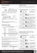
retrotouch IzJeeirLalSirodtLcts INTELLIGENT DIMMER MODULE.WIRING DIAGRAM OneWay Operation MODE SETTING How to set TEauto or LE Mode (Factory default TEauto mode): NOTE: The Dimmer must always be connected to the LINE side of the load. Two or more dimmers MUST NOT be connected in parallel or series to control the same load from two different locations. Retrotouch, Unit 3 Stockwell works, Crawley, West Sussex, RHI0 ITN Tel: +44(0)1293 279 426 Fax: +44(0)1293 471 444 [email protected] www.retrotouch.co.uk
Open the catalog to page 2All Retrotouch catalogs and technical brochures
 Lithe Audio Price list
2 Pages
 Retrotouch Trade Price list
9 Pages


Archived catalogs
 ES2000 Hotel card key
2 Pages
 AC2300
2 Pages
 T2000 Mental Touch
2 Pages
 AP2300
2 Pages
 Electronic thermostat
2 Pages
 Intellegent Audio System
2 Pages
 Retrotouch catalogue
2 Pages