Catalog excerpts

Sealed joints for pressurised and non-pressurised water Thermal insulation Sound insulation
Open the catalog to page 1
OUR CONVICTION: FORWARD CONSTRUCTING. Not just to reflect the current state of building technology, but always to be a decisive step ahead – this is our promise. This is why we constantly achieve pioneering work in all product areas. Our employees consistently use their extensive practical experience and creativity to benefit our customers. Through regular collaborative dialogue with our target groups, we develop today the products which are needed tomorrow. With our dynamics we set consistently milestones in building technology – yesterday, today and tomorrow. This is what we mean by...
Open the catalog to page 2
Sealing system Seam sheet for leak-proof construction joints Combined seal and equipotential bonding conductor Joint tape connection Pre-break elements for in-situ concrete walls Pre-break elements for precast parts walls Formwork element incl. seal Combined spacer, positioning gauge and joint shuttering 40 PENTAFLEX® pipe lead-throughs 46 PENTAFLEX® sump well 50 PENTAFLEX® OPTI wall strengtheners Sound attenuating cage Leak-proof penetration Prefabricated well Reinforcement attachment for leak-proof connections We are always there for you. We will be wherever you are.
Open the catalog to page 3
DESIGN AND CONSTRUCTION OF COMPONENTS IMPERMEABLE TO WATER* FUNDAMENTALS OF SEALING TECHNOLOGY ACCORDING TO WATER PROOFING GUIDELINES DESIGN BASICS In order to prevent ingress of water into structures, water impermeable reinforced steel structures, so-called "white tanks", have been fabricated for over 30 years. Thanks to these long years of practice and experience, this method of construction represents an economical way of stopping the ingress of water. Furthermore, the water proofing guidelines represent the generally recognized current technical standard with regard to the "white tank"....
Open the catalog to page 4
DESIGN OBJECTIVES DEFINING THE WATER PROOFING GUIDELINES A design of the arrangements must be carried out and the defined designs documented. For designs in accordance with water proofing guidelines, close collaboration between the different design areas is necessary. The water proofing guidelines determine and define the specifications for concrete structures impermeable to water. These are regulated in relationship to the stress and utilisation classes. THE FOLLOWING ARE THE PARTICIPANTS: ▪▪ Object designer/architect ▪▪ Geo-technician (if required) ▪▪ Bearing structure designer/water...
Open the catalog to page 5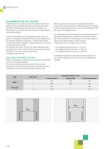
REQUIREMENTS ON THE CONCRETE adhering to the concrete cover, the required reinforcement location, joint sealing and the mounting components. In addition to all the other required features, it must also be possible to fulfil the support and sealing function. In the selection of a suitable concrete it should be noted that, in addition to the requirements arising from the exposure classes from DIN 1045 pertaining to the structural component, the requirements on a concrete with high resistance to water ingress must also be satisfied. A sufficient workability can be guaranteed by flow class F3...
Open the catalog to page 6
UTILISATION CLASS Proof of impermeability to water is an additional proof of fitness for purpose for DIN 1045-1, Clause 5.4.1, Section 2. LIMITING THE CRACK WIDTH For bending cracks resulting from stress and forces it must be proved for utilisation class A, stress class 1, that the pressure zone height (x) satisfies the condition x ≥ 30 mm and ≥ 1.5 · Dmax, whereby Dmax is the largest diameter of the aggregate. If there is an acceptable temporary ingress of water through separating cracks for stress class 1, the calculated widths of the separating cracks in relationship to the pressure...
Open the catalog to page 7
REINFORCEMENT AND CONSTRUCTION REGULATIONS The configuration of the reinforcement in the structural components must be designed such that it is possible to have a faultless insertion and compaction of the fresh concrete. Water proofing components of stress class 1 should be fabricated with a double-sided mat reinforcement composed of longitudinal and transverse reinforcement. The exception to this are prefabrications of stress class 2. The construction joints must be defined by the designer and represented in a blueprint. In accordance with the defined stress and utilisation class, all...
Open the catalog to page 8
PRACTICAL INSTRUCTIONS Extract from the practical instructions for the basic blueprint "Method of construction with reduced force loading": CONSTRUCTION SYSTEM FOR FLOOR SLABS At least one layer of PE film must be laid on a sub-base underneath the floor slab. The minimum thickness of the floor slab is based on the water proofing guidelines. For pressurised water this is 250 mm. The concrete cover of the upper layer of reinforcement is the responsibility of the building contractor and must be precisely complied with. This is a prerequisite for the pressurisedwater- tight installation of the...
Open the catalog to page 9
JOINT PLATE APPLICATION AREA PENTAFLEX KB® elements are fully coated on both sides with a special coating. The connection of the special coating with the fresh concrete reliably prevents water infiltrating the joint system. A concrete covering of 30 mm is enough to withstand a water pressure of 5.0 bar*. The high elasticity of the coating ensures a secure seal when the concrete components shrink. The individual elements are 2.00 m long and 167 mm or 80 mm high. They are provided with a divided protective film on both sides that is only removed immediately before concreting. ▪▪ Approved at...
Open the catalog to page 10
TECHNICAL INFORMATIONS PENTAFLEX KB® 167 ▪▪ Individual elements made from galvanised sheet steel fully coated ▪▪ Dimensions: l = 2.00 m b = 167 mm t = 1.2 mm ▪▪ Fixed to the reinforcement with 1 retaining stirrup per metre (see page 14) ▪▪ Embedment depth: ≥ 30 mm ▪▪ Watertight to 5.0* bar ▪▪ Application: Construction joints in wall/base, wall/wall and floor/floor areas PENTAFLEX KB® 80 ▪▪ Individual elements made from galvanised sheet steel fully coated ▪▪ Dimensions: l = 2.00 m b = 80 mm t = 1.2 mm ▪▪ he assembly is carried out using KB 80 stirrups which are T attached to the wall...
Open the catalog to page 11All PohlCon catalogs and technical brochures
-
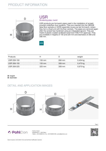
USR
2 Pages
-
Cable trays
446 Pages
-
Mesh cable trays
20 Pages
-
SHEAR DOWELS JSD+
40 Pages
-
UNICON® FAST CONNECTION SYSTEM
16 Pages
-
RAPIDOBAT® FORMWORK TUBES
32 Pages
-
SHEAR DOWELS HED
16 Pages
-
KUNEX® JOINT TAPES
28 Pages
-
ISOMUR® PLUS WALL BASE ELEMENTS
16 Pages
-
SOUND INSULATION
44 Pages


