Catalog excerpts

Mesh cable trays Assembly instruction
Open the catalog to page 1
Assembly instruction | Mesh cable trays | General notes General notes The support systems for mesh cable trays are to be planned according to engineering standards. The permissible torque must be observed for all screw connections. A legend of the symbols and an index can be found on page 3. Cutting and separating work Carry out cutting and separating work with the utmost care and in compliance with occupational health and safety regulations. Ex. fig. mesh cable tray cover GD 50-06 Galvanising All cut and separation points are to be galvanised on site with cold zinc paint (KZF)* or cold...
Open the catalog to page 2
Assembly instruction | Mesh cable trays | Legend Legend Symbols Wear safety goggles Wear hearing protection Observe tightening torque for fastening elements Index Mesh cable trays G 50 U-shaped mesh cable tray, height = 53 mm G 100 U-shaped mesh cable tray, height = 103 mm GI C-shaped mesh cable tray, height = 60 mm GTDW G-shaped mesh cable tray GTD 30 W-shaped mesh cable tray Covers GD Mesh cable tray cover GDR Mesh cable tray cover with turning bolts GID Mesh cable tray cover GIDR Mesh cable tray cover with turning bolts GD-SW Storm protection angle GID-SW Storm protection angle...
Open the catalog to page 3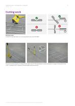
Assembly instruction | Mesh cable trays | Cutting work PohlCon | PUK Cutting work Bolt flush cutter Create the required mesh cut-outs using a bolt flush cutter 40° (BBS)*. The top illustration shows a U-shaped mesh cable tray G 50-40 assembled for a bend installation. Except for the lateral wires (G 50 = 2 pieces/G 100 = 3 pieces), all wire braces must be removed. * The item mentioned is not included in the scope of delivery and must be ordered s
Open the catalog to page 4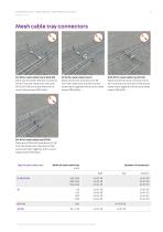
Assembly instruction | Mesh cable trays | Mesh cable tray connectors Mesh cable tray connectors GV 30 for mesh cable tray G 50/G 100 Place one GV 50/GV 100 with connector GV 30* from the inside onto the other GV 50/GV 100 and screw them with a round-head screw (FRSV 8x16). GV 30 for mesh cable tray GI Place one GI with connector GV 30* from the inside onto the other GI and screw them together with a round-head screw (FRSV 8x16). GVD 30 for mesh cable tray GTD 30 Place one GTD 30 with connector GVD 30* from above on the other GTD 30 and screw them together with a round-head screw (FRS...
Open the catalog to page 5
Assembly instruction | Mesh cable trays | Mesh cable tray connectors Mesh cable tray connectors 1 Insert connectors from the inside between the longitudinal wires. Mount bottom connector on opposite mesh cable tray. Engage with slotted screwdriver and lock the bending tab (from inside or outside). Position the cross wire in the guide on one side and snap it into place from the bottom opposite the beam. Type of mesh cable tray Width of mesh cable tray [mm] Snap-in connector Number of connectors Side The connector is not compatible with G 50 widths 400-600 or G 100 wi
Open the catalog to page 6
Assembly instruction | Mesh cable trays | Horizontal changes of direction Horizontal changes of direction Width of mesh cable tray [mm] Width of Number mesh cable GVU/GVK tray [mm] for side Mesh cable tray branch at corners for U-shaped mesh cable trays G 50/G 100 Remove the wire braces corresponding to the illustration for the mesh cable trays with bolt flush cutter (BBS)*. Slide the G 50‘s/G 100‘s over each other and screw them together with connectors (GV 30 and GVD 30)* and round-head screws (FRSV 8x16 and FRS 8x25). Width of mesh cable tray [mm] Standard mesh cable tray branch for...
Open the catalog to page 7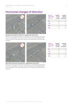
Assembly instruction | Mesh cable trays | Horizontal changes of direction Horizontal changes of direction Width of mesh cable tray [mm] Standard mesh cable tray branch for C-shaped mesh cable tray GI Remove the wire braces as shown in the illustration for the mesh cable trays using a bolt flush cutter (BBS)*. Join the GI‘s, screw the connectors (GV 30 and GVD 30)* from the inside onto the mesh cable trays with round-head screws (FRSV 8x16 and FRS 8x25). Width of mesh cable tray [mm] Mesh cable tray branch with radius for C-shaped mesh cable tray GI Remove the wire braces as shown in the...
Open the catalog to page 8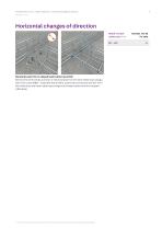
Assembly instruction | Mesh cable trays | Horizontal changes of direction Horizontal changes of direction Width of mesh cablte tray [mm] 80 - 130 Standard branch for G-shaped mesh cable tray GTDW Remove the wire braces as shown in the illustration for the mesh cable trays using a bolt flush cutter (BBS)*. Assemble the GTDW‘s, screw the connectors (GV 30)* from the inside onto the mesh cable trays using round-head screws with short square (FRSV 8x16). * The item mentioned is not included in the scope of delivery and must be ordered separately.
Open the catalog to page 9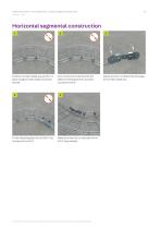
Assembly instruction | Mesh cable trays | Horizontal segmental construction Horizontal segmental construction 1 Position the mesh cable tray and fix it in place using the mesh cable connector (GV 30)*. Fit the clamping piece for the GVK* into the slots of the GVU*. First mount all connectors (GV 30)* before screwing the first universal connector (GVU)*. Make sure that the curved sides of the GVU* face inwards. * The item mentioned is not included in the scope of delivery and must be ordered separately. Adjust the GVU* to determine the angle of the mesh ca
Open the catalog to page 10
Assembly instruction | Mesh cable trays | Horizontal segmental construction Horizontal segmental construction U-shaped mesh cable tray G 50-06 Cutting work to create: 2 mesh cutouts Inner radius: 130 mm U-shaped mesh cable tray G 50-10/G 100-10 Cutting work to create: 2 mesh cutouts Inner radius: 90 mm U-shaped mesh cable tray G 50-20/G 100-20 Cutting work to create: 4 mesh cutouts Inner radius: 250 mm * The item mentioned is not included in the scope of delivery and must be order
Open the catalog to page 11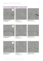
Assembly instruction | Mesh cable trays | Horizontal segmental construction Horizontal segmental construction U-shaped mesh cable tray G 50-30/G 100-30 Cutting work to create: 6 mesh cutouts Inner radius: 390 mm U-shaped mesh cable tray G 50-40/G 100-40 Cutting work to create: 8 mesh cutouts Inner radius: 550 mm U-shaped mesh cable tray G 50-50/G 100-50 Cutting work to create: 10 mesh cutouts Inner radius: 700 mm * The item mentioned is not included in the scope of delivery and must be orde
Open the catalog to page 12All PohlCon catalogs and technical brochures
-
 USR
USR2 Pages
-
 Cable trays
446 Pages
-
 SHEAR DOWELS JSD+
40 Pages
-
 UNICON® FAST CONNECTION SYSTEM
16 Pages
-
 RAPIDOBAT® FORMWORK TUBES
32 Pages
-
 SHEAR DOWELS HED
16 Pages
-
 KUNEX® JOINT TAPES
28 Pages
-
 ISOMUR® PLUS WALL BASE ELEMENTS
16 Pages
-
 SOUND INSULATION
44 Pages
-
 PENTAFLEX® SEALING SYSTEM
60 Pages