

ZOOM-Z180DD

ZOOM-Z180DD
The adjustable infrared photocell models ZOOM-Z180DD, FIRE-F180DD, and IR5001PS180DD operate with a power supply of 13.5 to 24 Vac/dc, with limits of 18-35Vdc and 15-28Vac. They have a maximum range of 20 meters and power absorption of 25mA for TX and 35mA for RX. The output relay contact supports up to 500mA and 48Vac/dc. The protection rating is IP 55 according to EN 60529 standards.
To set up the photocell, DIP switches are used. DIP1 and DIP2 set the photocell code, which must match the receiver's code. DIP3 should be ON for a single pair of photocells and OFF for two to four pairs, requiring synchronization via the SYNCHRO terminal. DIP4 is not used and should remain OFF. The JUMPER controls power, open for low and closed for high power. For relay delay, DIP2 SX ON introduces a 300ms delay, useful in conditions like heavy snowfall to prevent frequent disconnections.
To open the photocell, use a screwdriver between the cover and the wall. Ensure proper alignment using LED indicators for signal quality and synchronization. The photocell includes features like wall-mount fixing screws and a rotating block for adjustment.
The devices comply with EC directives 89/336/CEE and 93/68/CEE, ensuring conformity with relevant safety and performance standards.
For optimal performance, ensure correct DIP switch settings and synchronization when using multiple photocells. Consider environmental conditions like snow, which may require adjusting the relay delay settings.
Catalog excerpts

Fotodispositivo infrarosso regolabile 180° Digitale Adjustable infrared photocell 180° Digital Photocellule avec rotation 180° Digital ZOOM-Z180DD FIRE-F180DD IR5001PS180DD Potenza segnale Power signal Puissance signal Istruzioni ed avvertenze Instructions and warnings Instructions et notices d’emploi RX LED-C alignment OK=ON LED-B signal quality DIP 1 e 2 impostazione CODE, deve essere uguale al CODE del RX. DIP 3 ON (default) se si usa una sola coppia di fotocellule Z180DD. DIP 3 OFF se si usano due o max quattro fotocellule Z180DD, per la loro sincronizzazione è importante collegare tra loro tutti insieme i TX al morsetto 3 SINCRO. DIP 4 in OFF!! (default) non usato. JUMPER aperto minima potenza, chiuso massima potenza. DIP1 and DIP2 need to set up the photocell code, which should be the same as the CODE of the receiver. DIP3 ON (default) if you use only one pair of photocell Z180DD. DIP3 OFF if you use two or maximum four photocells Z180DD, for the syhnchronisation it is important to connect all transmitters to the terminal board 3 SYNCHRO. DIP4 in OFF!! (default) not used. JUMPER open for low power, closed high power. DIP1 et DIP2 pour établir le CODE , qui doit être le même au CODE du recepteur. DIP3 ON (default) si on utilise seulement une paire de fotocéllules Z180DD. DIP3 OFF si on utilise deux ou maximum quatres fotocéllules Z180DD, pour la synchronisation est important brancher au bornier 3 synchro,toutes les émetteurs ensemble. DIP4 en OFF!! (default) pas utilise. JUMPER basse puissance, haute puissance. DIP1 on le left , should be in OFF position, DIP2 on the left ON you will have a delay of intervention of the relay about 300ms. DIP2 on the left OFF (see table in the next page). DIP1 (à gauche) doit être en OFF, DIP2 (à gauche) ON intervention du rele de 300mS. DIP2 (à gauche) OFF (voir tableau à la page suivante) LED-B signal quality NO! No good signal NO! Little good signal *Dip 1 / 2 SX: DIP 1 sx deve essere lasciato in posizione OFF, DIP 2 sx ON ritarda di circa 300mS l’intervento del relè. DIP 2 sx OFF (vedi tabella pag. sucessiva). LED-A sincro pause... pause
Open the catalog to page 1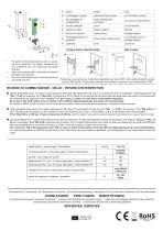
trous pour le branchement circuito stampato circuit imprimé sphere support rotating block blocage rotation viti fissaggio blocco di rotazione fixing screws rotating block vis de fixation pour le blocage rotation holes passage spin connection fori passaggio fili collegamento wallmount fixing screws viti fissaggio a parete Per aprire la fotocellula fare leva con un cacciavite tra il coperchio e la parete, aiutandosi con una protezione per non intaccare l’eventuale intonaco. Open the photocell with a screwdriver between the botton and the wall. Ouvrir la photocellule avec un tournevis entre le Protezione...
Open the catalog to page 2All NOLOGO catalogs and technical brochures
 OTTO-C
2 Pages
 ROX-QCD4
4 Pages
 ZOOM-Z1iDD
2 Pages
 ZOOM-Z180 / IR5001PS180
2 Pages
 ZOOM-Z180B
4 Pages
 ZOOM-LINE90
2 Pages
 ZOOM-Z1i
2 Pages
 FOTO-TOUCH
2 Pages
 RX2-XL
2 Pages
 RX2
RX26 Pages
 EKO-C
EKO-C2 Pages
 ROX-QC2
2 Pages
 SMART-QC2
2 Pages
 BANDY-CDE4
4 Pages
 BABY-ONE
2 Pages
 ACTIVE-A
12 Pages
 SMART-CD4
2 Pages
 RX4
RX44 Pages
 RX1
RX14 Pages
 START-UP
4 Pages
 TRANSCEIVER
24 Pages
 SWING-C
2 Pages
 SMILE-C
2 Pages
 START-S4XL
14 Pages
 LAMP
LAMP2 Pages
 SMART-ONE
2 Pages
 BABY-C
2 Pages
Archived catalogs
 CFSECUR
8 Pages
 START-S3 XL
18 Pages
 START-S0
8 Pages
 ACTIVE-S
5 Pages
 TRANSCEIVER
2 Pages
 BANDY-C4
2 Pages
 nologo 2011
42 Pages