Comfort 300
1 /8Pages

Comfort 300
1 /8Pages
Catalog excerpts
PRODUCT DATA Ventilation & passive heat recovery Domestic Passive Ventilation ^ OUTSTANDING INDOOR CLIMATE
Open the catalog to page 1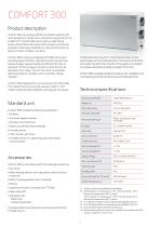
Comfort 300 Product description Comfort 300 is an energy-efficient ventilation system with heat recovery for homes with a ventilation requirement of up to 325 m3/h. Comfort 300 can be used in single-family homes, apartments and smaller office areas in commercial premises, where easy installation is required and where an optimum indoor climate is a priority. Comfort 300 includes an integrated CTS 602 control and operating panel, G4 filters, high performance counterflow heat exchanger, bypass damper and efficient EC fans as standard. The fans supply a constant air flow and can be adjusted in four...
Open the catalog to page 2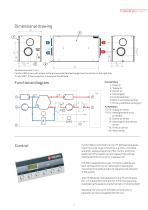
All dimensions are in mm. Comfort 300 shown with access to the primary side (heat exchanger) and connection to the right side. Turned 180 °, if the connection is desired to the left side. Functional diagram 1: Fresh air 2: Supply air 3: Extract air 4: Discharge air 5: Condensate drain 6: lectric and water heating E 7: Primary side (heat exchanger) Automation T2/T7: Supply air sensor T9/TC: eating element frost H protection T3: Extract air sensor T4: ischarge air and defrost D sensor T8: Fresh air sensor T10: Room sensor Comfort 300 is controlled from its CTS 602 operating panel featuring a wide...
Open the catalog to page 3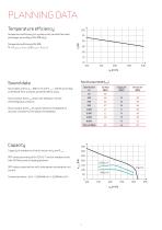
Planning data Comfort 300 Temperature efficiency Temperature efficiency for systems with counterflow heat exchanger according to EN 308 (dry). Temperature efficiency EN 308: t = (tsupply air-tfresh air)/(textract air-tfresh air) Sound data Sound output level (LWA) Octave band Hz Sound data are for qV = 200 m3/h and Pt, ext = 100 Pa according to EN 9614-2 for surfaces and EN 5136 for ducts. Sound output level LWA drops with falling air volume and falling back pressure. Sound output level LpA at a given distance will depend on acoustic conditions in the place of installation. Capacity of standard...
Open the catalog to page 4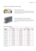
Capacity – Heating element (accessory) Electrical heating surface The electrical heating surface is fitted in the air inlet duct at a distance of min. 2 x duct diameter from the system’s fresh air inlet connecting pipe (normally min. 320 mm) and connected to the CTS 602 control panel and 230 V supply. The electrical heating surface can supply up to 0.9 kW of heat. Water heating element for internal fitting The water heating element is designed to be built into the system and must be connected to the primary heating supply and the CTS 602 control. The water heating element includes copper pipes...
Open the catalog to page 5
Accessories CO2 sensor With a CO2 sensor installed, the ventilation speed can be pre-programmed with CTS 602 to run at higher ventilation steps when CO2 reaches high level in the extract air. CO2 level is programmable. Water heating element incl. regulation The supply air temperature can always be raised to the required level using a water heating element. The water heating element is designed to be built into the unit and must be connected to the primary heating supply. Supplied with two-way adjustment valve, temperature sensor and frost thermostat. Electrical heating surface incl. regulation...
Open the catalog to page 6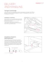
Transport and storage Comfort 300 comes in factory packaging that protects it during transport and storage. Comfort 300 must be stored in a dry place in its original packaging until installation. The packaging should only be removed immediately prior to installation. Installation conditions During installation, future service and maintenance should be taken into account. We recommend a minimum gap in front of and behind the unit of 60 cm. The unit must be installed level for the sake of the condensate drain. The condensate drain requires clearance of min. 12,5 cm under the drain nozzle. Min....
Open the catalog to page 7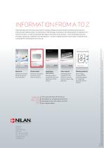
Product data General information about the solution and its benefits. Technical information to ensure correct choice of solution. Installation instructions Detailed guide for installation and initial adjustment of the solution. User manual Drawing material Detailed guide for regulation of the solution to ensure optimum day-to-day operation. Nilan is happy to make 2D CAD drawings available for integrated planning with the solution. Visit us at www.nilan.dk to find out more about our company and solutions, download further information and find your nearest dealer. Nilan A/S assumes no responsibility...
Open the catalog to page 8All Nilan A/S catalogs and technical brochures
 COMBI S 302 POLAR TOP BY NILAN
16 Pages
 VP 18 M2
16 Pages
 EM-BOX
4 Pages
 COMPACT P - CTS602 HMI
32 Pages
 COMFORT CT300/POLAR
20 Pages
 COMPACT P - SERIES
44 Pages
 Indoor Climate
36 Pages
 Heating Elements
8 Pages
 VPM 120-560 brochure
6 Pages
 VPM 600 3200 brochure
24 Pages
 Nilan Calculator brochure
8 Pages
 Compact p
16 Pages
 Em-box by NILAN
4 Pages
 Comfort 600
8 Pages
 Comfort 450
8 Pages
 Comfort 300 top
8 Pages
 Comfort 250 top
6 Pages
 The future is decentralised
16 Pages
 CTS 6000
4 Pages
 Comfort CT300
8 Pages

- Industrial heat pump
- Residential heat pump
- Air source heat pump
- Mechanical ventilation unit
- Ventilation controller
- Air/water heat pump
- Commercial heat pump
- Ventilation unit
- Residential ventilation unit
- Home ventilation unit
- Reversible heat pump
- Analysis software
- Hot water heat pump
- Steel structure software
- Industrial calculation software
- Centralized ventilation unit
- Heat-recovery ventilation unit
- Heat recovery unit
- Commercial ventilation unit
- Compact ventilation unit