F470
1 /76Pages
F470
1 /76Pages
Catalog excerpts
Installer manual Exhaust air heat pump NIBE F470
Open the catalog to page 1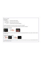
Quick guide Navigation Ok button (confirm/select) Back button (back/undo/exit) Control knob (move/increase/reduce) A detailed explanation of the button functions can be found on page 42. How to scroll through menus and make different settings is described on page 44. Set the indoor climate INDOOR CLIMATE The mode for setting the indoor temperature is accessed by pressing the OK button twice, when in the start mode in the main menu. Increase hot water volume 1X 2X To temporarily increase the amount of hot water, first turn the control knob to mark menu 2 (water droplet) and then press the OK button...
Open the catalog to page 2
Safety information _ _ Safety precautions _ _ Serial number_ Supplied components _ _ Removing parts of the insulation___ 3 The heat pump design _ Air treatment unit and compressor module_ 4 Pipe and ventilation connections_ General pipe connections_ _ Dimensions and pipe connections__ Climate system_ Installation alternative _ _ General ventilation connection___ Ventilation flow_ Adjusting ventilation _ _ Dimensions and ventilation connections__ Optional connections _ _ Connecting accessories _ _ Setting the heating curve _ _ 39 Menu 1 - INDOOR CLIMATE _ _ 46 Menu 4 - HEAT PUMP _ - 47 Electrical...
Open the catalog to page 3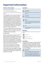
Important information Safety information This manual describes installation and service procedures for implementation by specialists. Explanation of symbols that may be present in this manual. The manual must be left with the customer. For the latest version of the product’s documentation, see nibe.eu. This symbol indicates serious danger to person or machine. This appliance can be used by children aged from 8 years and above and persons with reduced physical, sensory or mental capabilities or lack of experience and knowledge if they have been given supervision or instruction concerning use of...
Open the catalog to page 4
Safety precautions WARNING! Do not use agents to speed up the defrosting process or for cleaning, other than those recommended by the manufacturer. The apparatus must be stored in a room with no continuous ignition sources (e.g. naked flame, an active gas installation or an active electric heater). Must not be punctured or burned. Be aware that the refrigerant may be odourless GENERAL Pipe installation should be kept to a minimum. AREA CHECKS Before work is started on systems that contains combustible refrigerants, safety checks must be performed to ensure that the ignition risk is kept to a...
Open the catalog to page 5
• The actual filling quantity is appropriate for the magnitude of the space where the parts containing refrigerant are installed. • Ventilation equipment and outlet work correctly and without obstructions. • If an indirect refrigerant circuit is used, check whether the secondary circuit contains refrigerant. • All markings of equipment are visible and clear. Markings, signs and similar that are not clear must be replaced. • Refrigerant pipes and components are positioned in such a way that it is not likely that they be subjected to substances that can corrode components containing refrigerant,...
Open the catalog to page 6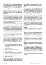
leak tracer must not be a potential source of ignition and must be suitable for the relevant refrigerant. The leak tracing equipment must be set and calibrated for the relevant refrigerant, to ensure that the gas concentration is a maximum of 25% of the lowest combustible concentration (Lower Flammability Limit, LFL) of the relevant refrigerant. Leak detection fluids are suitable for use with most refrigerants but the use of detergents containing chlorine shall be avoided as the chlorine may react with the refrigerant and corrode the copper pipe-work. If a leak is suspected, all naked flames...
Open the catalog to page 7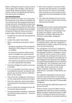
Before refilling the system, pressure test it with oxygen-free nitrogen. Leak test the system after filling but before using the system. Perform an additional leak test before leaving the installation. Before the device is taken out of operation, the technician must without exception be very familiar with the equipment and all its component parts. Good practice prescribes that all refrigerant is collected safely. Before the collected refrigerant can be reused, oil and refrigerant samples must be taken, if analysis is required. There must be a power supply when this task is started. 1 Familiarise...
Open the catalog to page 8
components must be sealed, to prevent ignition if any refrigerant should leak out. Contact the manufacturer if you are in any doubt. Return the collected refrigerant to the refrigerant supplier in the correct collection container and with the relevant Waste Transfer Note. Do not mix refrigerants in collection devices or containers. If compressors or compressor oil are to be removed, ensure that the affected device is drained to an acceptable level to ensure that no combustible refrigerant remains in the lubricant. Compressors must be drained before being returned to the supplier. The compressor...
Open the catalog to page 9
Chapter 11 Important information NIBE F470
Open the catalog to page 10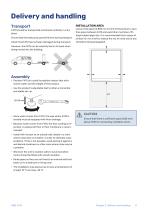
F470 should be transported and stored vertically in a dry place. Ensure that the heat pump cannot fall over during transport. Check that F470 has not been damaged during transport. However, the F470 can be carefully laid on its back when being moved into the building. • Position F470 on a solid foundation indoors that withstands water and the weight of the product. • Use the product's adjustable feet to attain a horizontal and stable set-up. • Since water comes from F470, the area where F470 is located must be equipped with floor drainage. • Because water comes from F470, the floor coating is...
Open the catalog to page 11
Supplied components Pull the panel towards yourself. 3 Outdoor temperature sensor (BT1) Current sensor LOCATION The kit of supplied items is placed on top of the product. Remove the upper panel by pulling it straight out. Remove the screws from the lower edge of the front panel. Remove the screws from the upper and lower edges. Lift the panel out at the bottom edge and up. Chapter 2 | Delivery and handling
Open the catalog to page 12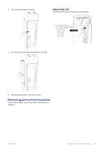
Twist the panel slightly outwards. Grip the handle and pull straight out as illustrated. Move the panel backwards and slightly to the side. Assembly takes place in the reverse order. Removing parts of the insulation Parts of the insulation can be removed to facilitate the installation. Chapter 2 | Delivery and handling
Open the catalog to page 13All NIBE Energy Systems catalogs and technical brochures
 SMO 40
48 Pages
 S1156/S1256
16 Pages
 Sustainability is in our nature
44 Pages
 F1345
F134572 Pages
Archived catalogs
 EMINENT
2 Pages
 NIBE Ground source
36 Pages
 F2026
F20264 Pages
 nibe
nibe32 Pages
 Domestic Boilers
4 Pages
 NIBE™ F2016
32 Pages
 Solar FP215 series
2 Pages
 NIBE™ F2300
32 Pages
 NIBE Energy systems
8 Pages
 NIBE Water heaters
24 Pages
 1145/VPAS FP215 P / PL
2 Pages
 F1255
F125522 Pages
 F1155
F115522 Pages
 F1345
F134528 Pages
 NIBE™ F2120
2 Pages
 NIBE GROUND SOURCE
36 Pages
 NIBE™ F2030
16 Pages
 NIBE™ F370
16 Pages
 NIBE™ F470
16 Pages
 NIBE product range
64 Pages
 NIBE Accessories
20 Pages
 F1255
F125520 Pages
 NIBE S Series heat pumps
48 Pages
 NIBE PRODUCT RANGE 2016
32 Pages


- Boiler
- Indoor boiler
- Domestic boiler
- Residential heat pump
- Air source heat pump
- Industrial thermostat
- Industrial solar panel
- Outdoor heat pump
- Industrial water heater
- White thermostat
- Mechanical ventilation unit
- Programmable thermostat
- Heating thermostat
- Digital thermostat
- Vertical water heater
- Air/water heat pump
- Inverter heat pump
- Energy rating heat pump
- Electric water heater