

CABLE TRAY SYSTEMS

CABLE TRAY SYSTEMS
MP Husky is a prominent manufacturer of cable tray systems, known for its innovative and environmentally friendly products. The company emphasizes customer support, environmental protection, and advanced engineering.
Cable tray systems provide structural support for cables in various applications. The main types include Ladder, Trough, Center Rail, Wire Basket, and Channel, each designed for specific uses such as power or data communication cables.
The document provides detailed technical data on materials, construction, corrosion resistance, electrical design, and grounding, including specifications for different tray types and their applications.
Cable trays are made from corrosion-resistant metals like aluminum and steel. The choice of material depends on economic considerations and installation requirements, such as conductivity and corrosion resistance.
The document outlines NEMA and CSA load classifications, detailing load capacity per foot and support span for various classes, crucial for selecting the appropriate tray for specific applications.
MP Husky adheres to high-quality standards like ISO 9001 and NEMA VE-1, and is compliant with nuclear standards, undergoing audits every three years to ensure quality assurance in nuclear applications.
The document lists standards and certifications, including ANSI, ASME, and AWS, ensuring compliance with industry requirements for quality and safety.
MP Husky serves over thirty nuclear plants worldwide, being the only cable tray manufacturer compliant with 10CFR50 Appendix B, with regular audits to maintain its quality assurance program.
MP Husky's cable tray systems are engineered to meet diverse industrial needs, backed by rigorous quality standards and a commitment to innovation and customer satisfaction.
MP Husky manufactures cable trays using various materials, each with distinct properties and applications. Steel trays are cost-effective and strong but have poor corrosion resistance. Stainless steel offers enhanced corrosion resistance, suitable for high durability environments. Galvannealed steel improves paintability and corrosion resistance. Fiberglass trays are non-conductive and corrosion-resistant, suitable for harsh environments.
Corrosion in metals is primarily due to electrochemical phenomena. Zinc coatings provide protection, with effectiveness varying based on environmental conditions. Indoor environments generally offer longer protection for zinc coatings compared to outdoor settings.
Steel cable trays can be protected from corrosion through metallic coatings. The choice of finish depends on environmental conditions and application requirements.
For environments prone to galvanic corrosion, selecting metals close together in the galvanic series is advised. Protective coatings or galvanization can help protect steel. Aluminum alloys benefit from a self-healing oxide film that provides corrosion resistance.
Aluminum's corrosion resistance is due to its oxide film. Problems in aluminum installations are rare and usually due to incorrect alloy choice or exposure conditions. The 6000 series alloys are noted for good resistance in industrial and marine environments.
Zinc coatings on steel show a linear corrosion rate in various atmospheres, with longevity proportional to thickness.
Design conditions consider weather factors, load types, and maximum allowable stresses. Loads are categorized into dead, live, and dynamic loads, with additional subdivisions for practical load classification.
The National Electrical Safety Code recognizes three degrees of loading due to weather: heavy, medium, and light. Modifications are necessary for cable tray systems concerning ice, snow, and wind loadings.
Design loadings for cable trays are based on maximum allowable stress and vary with span, type, and width of the tray. Load tables provide guidance for standard supports.
Dynamic loads result from motion, such as cables being dropped. Inertia loads occur when the structure is in motion, requiring special design considerations.
Class 1 and Class 2 loading specifications are similar to Class 3, which requires a lateral, horizontal wind pressure of 25.6 lbs. per square foot on a 4-inch deep tray without ice-coating.
Limiting deflection in cable tray systems is important for aesthetic reasons. Methods to decrease deflection include decreasing stress by reducing the bending moment and increasing the depth of the tray.
Grounding is crucial for safety, protecting against faults caused by electrical disturbances. Effective grounding should be permanent, continuous, and have low impedance.
The document discusses the electrical design of cable trays, emphasizing the need for high current carrying capacity during faults.
Guidelines for installing multiple-conductor cables in various tray types are provided, ensuring the total diameter of cables does not exceed the tray width.
The document outlines specifications for cable trays, focusing on the cross-sectional area limits for different types of trays.
Detailed procedures for sizing cable trays for single conductor cables are provided, including calculations and examples.
Formulas are provided for calculating deflection for loads smaller than those shown in load deflection tables.
The document includes selection tables for different NEMA classes and materials, detailing load capacities and dimensions for aluminum and steel trays.
Information on safety factors, rung options, and standard dimensions for fittings and splice plates is included.
This document is a technical guide from MP Husky, detailing specifications, procedures, and standards for cable trays, specifically focusing on I-Beam and Husky Trough designs.
The document outlines different NEMA classes for cable trays, specifying load capacities, tray heights, load depths, and top flange widths.
The document includes a numbering system for identifying tray types, materials, rung spacing, and dimensions.
The document adheres to NEMA standards, specifying classes such as 12A, 12B, 12C, 20A, 20B, 20C, 24B+, and 24C+.
MP Husky recommends using I-Beam style trays for customers preferring this design or for expanding existing installations.
Detailed loading tables are provided for various spans and widths, indicating load limits and safety factors.
The tables provide load capacities in pounds per foot for different spans and widths.
This document serves as a comprehensive guide for selecting and configuring cable trays, ensuring compliance with NEMA standards.
The document provides technical specifications and data for MP Husky's aluminum ventilated and solid bottom cable trays.
- Depth: Nominal depths of 4-1/2, 6, 7, 8, and 10 inches.
- Widths: Available in 6, 9, 12, 18, 24, 30, and 36 inches.
- Lengths: Standard lengths include 10' (120"), 12' (144"), 20' (240"), and 24' (288").
- Materials: Primarily aluminum, with options for solid or ventilated bottoms.
- Tray Types: Includes JA, JB, MB1, MC, YA2, XA, X, X1, X7, X71, L1, D1.
- Assembly of part numbers uses a color-coding system to denote specific features such as corrugated bottoms and rung spacing.
- Safety Factor: 1.5 NEMA Standard.
- Compliance with NEMA and CSA standards for various tray types.
- Tables provide load capacities for different spans and widths, with specific notes on corrugated bottoms and rung spacing.
- For the most current data, users are advised to visit the MP Husky website.
The document provides detailed technical specifications and guidelines for Husky EMI (Electromagnetic Interference) Enclosures, designed to protect control and instrumentation cables from electromagnetic and electrostatic interference in industrial settings.
- The EMI enclosures are designed to shield low-level control circuits from interference over a frequency range of 60 Hz to 100 kHz.
- Materials used include ASTM A653-G90 Steel, with all enclosures being hot-dip mill galvanized.
- Minimum electrostatic attenuation is specified at 86 dB, and electromagnetic attenuation ranges from 9 dB to 55 dB.
- Installation involves clamping the enclosure to support structures and using a wrap-around splice for joining sections.
- The manufacturer must certify that the enclosures meet specified shielding efficiencies, supported by evaluation tests and technical data.
- Use twisted parallel pairs that are shielded and grounded.
- Loading tables provide span and width specifications for various cable tray configurations, indicating load capacities and attenuation values.
Husky EMI enclosures offer a cost-effective solution for protecting control cables from interference, facilitating easy installation and maintenance while ensuring compliance with industry standards.
The document outlines the specifications for hot-dip galvanizing protective coverings, which must conform to ASTM Standards.
The contractor is required to submit a complete schedule of materials and equipment for approval within thirty days after the contract award.
The cable trays are made from ASTM-A653 G90 Steel with a standard finish.
Guidelines for installation include the use of standard self-drilling sheet metal screws and optional holding devices like banding and clamps.
The document details the numbering system for various fittings, including horizontal and vertical bends, crosses, and tees.
All channels have a safety factor of 1.5 as per NEMA standards.
This document provides detailed specifications and installation guidelines for MP Husky cable tray systems, including various accessories and support materials.
The document outlines the specifications for different types of cable trays and accessories.
Installation procedures for mid-span splices and hold down clips are provided.
The document references NEMA VE-2 for expansion guide recommendations.
A variety of accessories are detailed, including single and double hold down clips, expansion guides, hanger clips, and trapeze support kits.
The document lists support materials such as hanger rods, suspension channels, and beam clamps.
The tables provide catalog numbers, material types, and dimensions for each accessory and support component.
The document emphasizes the importance of using the correct hardware and following installation guidelines to ensure the safety and reliability of the cable tray systems.
This document is a technical catalog detailing various support materials and components for cable trays, including clamps, hangers, brackets, and covers.
These are used for supporting hanger rods on I-beams and wide flange beam sections.
These clamps come with a hook bolt and swivel clevis, available in plated steel and SS 316.
Designed for supporting vertical ladders or troughs, these hangers come with necessary mounting hardware.
Suitable for American Standard channels with a flange width of 3-1/4” or less.
These supports vary based on load, spacing, and distance from the wall.
Various types of wall brackets are available for supporting trays and channels.
These brackets are used for supporting multiple ladders or long spans.
Designed for use with strut framing, these brackets support different tray widths and loads.
The catalog includes a variety of covers to protect cables from environmental elements.
This document provides detailed specifications and descriptions of various components and accessories used in wire basket systems.
- Bolt-Nut Set: Consists of BF Bolt and BF Nut, shipped in quantities of 100.
- Bolt-Staple Set: Includes BF Bolt Set and BF Staple, shipped in quantities of 100.
- SSC Hold Down: Used for creating adjustable fittings or as a center hanger support.
- Simple SL: Used to mount wire baskets to walls.
- Assembly Instructions: Details the number of accessories required for different widths of wire baskets.
- Zinc Rich Paint: Recommended for coating field cut ends to protect against corrosion.
- Drop-Out Plate: No hardware required for securing to wire basket.
- Multi Union Joint: Used for field fabrication of fittings.
- Vertical Splice Plates: Requires two plates for creating vertical fittings.
- Wall Support: Attached using two Bolt-Staple Sets.
- Trapeze Hangers: Designed for use with 1/4” threaded rod.
- Raised Floor Supports: Used to raise wire baskets off the floor.
- All components are available in different finishes, including EZ and HDGAF.
The document outlines the specifications for the Husky Wire Mesh Cable Support System, specifically the BF2R and BFR Series.
The assembly instructions detail the required accessories for different tray widths.
The Husky Centray system is highlighted for its center-supported cable trays made from 6063-T6 high-strength aluminum.
The Husky Centray system offers several advantages, including reduced installation costs and easy access for cable loading and inspection.
The document lists various connectors and couplings available for the Husky Centray system.
The document provides detailed specifications and guidelines for MP Husky's cable tray systems, focusing on various components, installation procedures, and material properties.
The document lists part numbers and dimensions for various components such as vertical hinge connectors, stabilizer bars, wall mounts, and rail end caps.
Includes details on wall brackets, barrier strips, rung caps, and grounding straps.
MP Husky's fiberglass cable trays are made from glass fiber-reinforced plastic, offering non-conductive, non-magnetic, and corrosion-resistant properties.
Installation should comply with NEMA VE-2 standards and the National Electrical Code.
Provides a comprehensive list of chemical environments and their compatibility with polyester and vinylester resin systems.
Includes load capacity comparisons with steel and the effects of temperature on material strength.
Instructions on how to order cable trays, including series, material, rung spacing, width, and length specifications.
The document provides detailed specifications and descriptions for various cable tray systems and components manufactured by MP Husky.
- Cable tray systems are designed to avoid damage to cable insulation with no burrs or sharp edges.
- Fittings have the same load capacity as straight sections and are available in various radii.
- Tray sections are available in lengths of 10, 12, 20, 24, or 30 feet.
- Longitudinal members are made from extruded aluminum or galvanized steel.
- Transverse members are designed to prevent moisture collection.
- Splice connections must not exceed 330 microhms resistance.
- Splice connectors are high-pressure bolted with a minimum of four bolts per connector.
- Husky trays have a load safety factor of 1.5 based on destruction load.
- Trays are labeled with cross-sectional area and load capacity to ensure system adequacy.
- Trays are manufactured in accordance with NEMA VE1 standards.
- Details on various fittings, clamps, and hangers are provided.
- Wire mesh trays are designed for ventilation and heat dissipation.
- Fiberglass trays meet NEMA FG-1 standards.
- Manufactured from high-strength aluminum, with specific design features for enhanced performance.
The document outlines the specifications for cable trays and bus systems manufactured by MP Husky.
- Dimensions: The spine and rungs have specified minimum thicknesses and dimensions.
- Construction: The spine is punched to minimize distortion.
- Wall Mount Trays: These trays are mounted with spacers to accommodate wall irregularities.
- Widths: Measurements are taken inside the rungs.
- Manufacturing Standards: Trays must be manufactured by a NEMA member.
- Design: Systems must be free of burrs and sharp edges.
- Fittings: Must have the same load capacity as straight sections.
- Material: Options include aluminum, galvannealed steel, and stainless steel.
- Splice Joints: Resistance should not exceed 330 microhms.
- General Requirements: Suitable for indoor or outdoor use.
- Construction: Made from aluminum alloy 6063-T6.
- Electrical Specifications: Conductors must have insulation rated for 90°C.
- Current Rating: The bus enclosure must have a continuous current rating of at least 1,000 amperes.
Catalog excerpts

CABLE TRAY & CABLE BUS TRAY SYSTEMS Support Powerful Reputations
Open the catalog to page 1
CABLE TRAY & CABLE BUB CABLE TRAY SYSTEMS Engineered to Support Powerful Reputations MP Husky was founded in 1952 and originally began operations as Husky Products. Over the following 50+years of leadership and service, MP Husky has gone through several transformations and mergers, including Husky/Burndy and Metal Products, thus leading to what is today MP Husky—America's leading manufacturer of Cable Tray and Cable Bus Power Distribution Systems. Throughout these changes,one thing has remained constant—the "Husky" drive to be the most reliable, highest quality, cost effective and innovative...
Open the catalog to page 2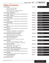
Table of Contents Technical Data Description and Applications Materials and Construction Corrosion Resistance—Loading—Deection Electrical Design and Grounding Husky Ladder—Flange-Out Numbering System, Loading Tables, Ordering Information Husky Ladder—Flange-In Numbering System, Loading Tables, Ordering Information Husky I-Beam Ladder Numbering System, Loading Tables, Ordering Information Husky Trough Numbering System, Loading Tables, Ordering Information Husky I-Beam Trough Numbering System, Loading Tables, Ordering Information Husky Way Numbering System, Loading Tables, Ordering Information...
Open the catalog to page 3
Introduction Decade after decade, for nearly 60 years, MP Husky continues to be the trusted and proven name in Cable Tray. With more systems installed in more industries and environments than any other manufacturer, you can rest assured MP Husky has the experience and capability to meet your most demanding requirements. As we begin another decade, MP Husky is stronger than ever and positioned to lead the industry with the latest innovations, eco-friendly products, and engineering and manufacturing technologies. Our focus continues to remain on providing unmatched customer support, investing in...
Open the catalog to page 4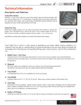
Technical Information Description and Selection Husky Wire Basket Techtray is a wire mesh cable tray system that utilizes high mechanical strength steel wire that is welded into a 2” x 2” grid system. Typically used to carry data communication and ber optic cables, with a high degree of exibility during installation due to capability and ease of fabricating ttings in the eld. Husky Pan Tray Husky Way straight sections are one piece formed pan that provides a smooth at bottom and a ll depth that is almost the same as the outside height of the tray. With a cover it provides complete protection...
Open the catalog to page 5
Technical Information Description and Selection NEMA LOAD CLASSIFICATION The National Electrical Manufacturers Association (NEMA) has standardized the classication of cable tray based on the load to be carried per foot, and the distance between span supports. The load per foot should include not only the cable, but additional load factors for wind, snow, ice, etc. For more information on loading, see page 14 in this section. NEMA CLASS SUPPORT SPAN (feet/meters) MP Husky manufactures Cable Tray in accordance with the latest NEMA Standards Publication VE1 and CSA Standard C22.2 No. 126.1 CSA LOAD...
Open the catalog to page 6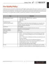
Our Quality Policy At MP Husky we are committed to producing only the highest quality products that meet or exceed our customers’ expectations and requirements. Our goal is to achieve 100% customer satisfaction by delivering the best products and services on time and defect free. We will achieve this individually and corporately through tested and proven processes and controls, in our Quality System, and with a constant focus and eort on continuous improvement. Item MP Husky Quality Program -Quality Assurance -Manufacturing Standards Certication Load Test Standards Cable Tray Standard Grounding...
Open the catalog to page 7
Nuclear Program MP Husky is audited in conformance with 10 CFR50 Appendix B - Nuclear Standards by the U.S. Nuclear Regulatory Commission. Appendix B to Part 50--Quality Assurance Criteria for Nuclear Power Plants and Fuel Reprocessing Plants - This appendix establishes quality assurance requirements for the design, manufacture, construction, and operation of those structures, systems, and components. The pertinent requirements of this appendix apply to all activities aecting the safety related functions of those structures, systems, and components; these activities include designing, purchasing,...
Open the catalog to page 8
Materials & Construction Cable tray systems are commonly fabricated from a corrosion-resistant metal or from a metal with a corrosion-resistant nish. The selection of the proper material is essentially an economic consideration. Non-Heat-Treatable Alloys—the initial strength of alloys in this group depends upon the hardening eect of elements such as manganese, silicon, iron and magnesium, singly or in various combinations. The non-heat treatable alloys are designated as 1000, 3000, 4000, and 5000 series. As these alloys are work-hardenable, further strengthening is made possible by various degrees...
Open the catalog to page 9
Materials & Construction Steel MP Husky oers cable trays and accessories in both the 304 and 316 series. These austenitic alloys are remarkable in several respects. Unlike the other two classes, they contain nickel in quantities from 4 to 22 percent, while the percentage of carbon is kept relatively low. When chromium is increased for improved corrosion resistance, nickel must also be increased to retain the austenitic structure. Steel cable trays are used principally in environments which are relatively free from corrosive attack. They are available with various types of corrosionresistant nishes;...
Open the catalog to page 10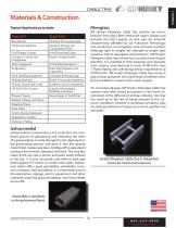
Materials & Construction Fiberglass Typical Applications include: Beer Barrels Chemical Equipment MP Husky’s Fiberglass Cable Tray systems are manufactured from glass ber-reinforced plastic shapes and provides the load capacity of steel, plus the inherent characteristics aorded by our Pultrusion Technology: non-conductive, non-magnetic and corrosion-resistant. Although light in weight, the strength to weight ratio surpasses that of equivalent steel products. MP Husky’s Fiberglass Cable Tray will not rust, nor does it ever require painting. It is available in both polyester and vinylester resin...
Open the catalog to page 11All MP Husky catalogs and technical brochures
 Wire Mesh Cable Tray
32 Pages
 Centray® Single Rail Cable Tray
16 Pages
 QUALIFICATIONS
32 Pages
 HUSKY FIBERGLASS
52 Pages
 WIRE BASKET CABLE TRAYS
32 Pages
 CABLE BUS
31 Pages