Group: Mitsubishi

Catalog excerpts
MOTOR CONTROL CENTERS Meeting increased requirements in compactness, performance and flexibility
Open the catalog to page 1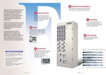
E ngineering Support Program up/down load, parameter management and motor history access, can all be accomplished via a handheld PDA. Mitsubishi Electric has supplied Motor Control Please note that changes to a specific sequence require the use of a PC. Centers to many countries throughout the world. Rapid globalization has stimulated diversification in all fields, fostering a The unique unit drawer structure and new, tiny 1/4 unit save on precious floor space. Up to 40 units can be accommodated in a single MCC section without compromise to the convenience of features such as fully...
Open the catalog to page 2
Type Applied standard Rated insulation voltage Rated operating voltage Rated busbar current Rated short-circuit withstand current Device capacity Incoming circuit breakers Power supply feeders Motor starters Installation Ambient temperature Relative humidity (no condensation) Ingress protection Internal separation Forms 1 to 4b Paint (Munsell No. 5Y 7/1) Paint or galvanized plating Max. number per m2 of floor space Electronic motor control & protection Short-circuit protection Short-circuit protection coordination Max. short-circuit interrupting capacity Doors and external panels Frame,...
Open the catalog to page 3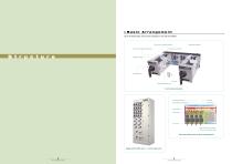
Basic Arrangement Up to 40 drawer-type units can be arranged on one side of the MCC. Main circuit connector (load side) Main circuit connector (supply side) Supply-side distributor Control circuit connector Magnetic contactor Drawer-type unit Fuse-link Switch-disconnector-fuse unit internal structure Supply-side distributor Grip (supply-side distribution) Control circuit Vertical busbar Supply-side Main circuit terminals (upper) Control circuit terminals (lower) Top cross-section view of panel compartments Single section MCC with 1/4, 1/2 & full width units TYPE-F MOTOR CONTROL CENTER...
Open the catalog to page 4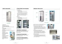
Main Assembly Field Cable Termination 1. 1/4 & 1/2 units 1 Main circuit cables Connect to the main circuit terminal block A1 2 Control circuit cables Connect to the control circuit terminal block A2 Since the main and control circuit terminal blocks for each unit are arranged within the vertical wireway, there is no need to open any unit door or draw out any unit in order to terminate field cables. 2. Other units 1 Main circuit cables Connect to the main circuit terminal block B1 2 Control circuit cables Connect to the control circuit terminal block B2 Busbar Structure Vertical earth busbar...
Open the catalog to page 5
Motor capacity Rated current (kW) (A) 0.2 Unit dimensions Switch-fuse Contactor Overload relay At 400 V AC, 50 Hz † A width of 1 corresponds to the entire available unit space. Several motor starter combination units demonstrating a range of the unit widths available Unit and cable compartments TYPE-F MOTOR CONTROL CENTER TYPE-F MOTOR CONTROL CENTER
Open the catalog to page 6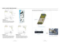
Unit Latch Mechanism Vertical busbar Supply-side grip Control circuit connector Please note that when the switch-disconnector is ON, the unit cannot be drawn out. Specifically, the unit door cannot be opened and 3 interlocks prevent the unit from being drawn out. Control circuit connector Load-side connector Unit Operating lever TOP VIEW FRONT VIEW Unit in LOCK position 1. LOCK position (operating lever = left) Springs Latches (locked) Latches for positioning and locking unit into place When the lever is in the LOCK position, the supply-side grips are in contact with the busbars and the...
Open the catalog to page 7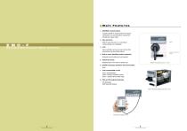
Main Features 1. MODBUS communications Transfer all EMC-F measurements and status information to a central location using 3-wire twisted pair copper cable. 2. New small size EMC-F EMC-F easily fits onto a 1/4 unit without compromising LCD readability. E M C - F Electronic Multi-function Motor Controller 3. LCD Each controller can have its own LCD so that parameters may be directly altered. Switch-disconnector handle 4. Built-in motor Start/Stop buttons (optional) External control buttons are not required. 5. Historical records Retained even in the event of power loss. EMC-F with optional...
Open the catalog to page 8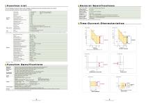
Function List General Specifications The LCD displays measured values, fault messages, parameters and motor operation history; all of which can be transmitted using the communications interface. Operation History Total run time Forward starts Reverse starts Trip count Overcurrent trip count Phase unbalance trip count Ground fault trip count Instantaneous overcurrent trip count Undercurrent trip count External trip count Instantaneous restart count EMC error code Trip history Operating status Operating current Ground fault current Cause Trip current After 9,999 hours (or counts), the 0 ~...
Open the catalog to page 9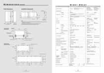
Dimensions (units:.™) Panel Dimensions Installation Dimensions Front view Side view' Foundation bolt 1. One foundation base can accommodate up to 2 panels. Additional bases are required for the installation of 3 or more panels. 2. Do not attempt to transport more than 2 mounted panels at one time 3. Foundation bolts (pictured right) will be supplied upon request. front space Foundation bolt hole (optionally supplied) - Panel frame Panel under-frame Embedded base (not supplied) Foundation base - 4 of 022 holes (front and rear) 8 of 022 holes (front and rear) TYPE-F MOTOR CONTROL CENTER Order...
Open the catalog to page 10
A MITSUBISHI ELECTRIC CORPORATION HEAD OFFICE: MITSUBISHI DENKI BLDG., 2-2-3, MARUNOUCHI, CHIYODA-KU, TOKYO 100-8310, JAPAN Please read the instruction manual before using the device. Revised publication, effective June 2005. Specifications subject to change without notice.
Open the catalog to page 11All MITSUBISHI ELECTRIC catalogs and technical brochures
-
 MSZ-HR R32
2 Pages
-
 MFZ-KT R32
2 Pages
-
 PLA-ZM-R32
2 Pages
-
 PLA-M R32
2 Pages
-
 PLA-SM R410A
2 Pages
-
 HVRF PLFY-WL-VFM-E
2 Pages
-
 PUMY-P R410A
2 Pages
-
 MSZ-LN R32
2 Pages
-
 2020 Product Catalogue
402 Pages
-
 Central Plant Solutions
24 Pages
-
 I-LIFE2 SLIM
6 Pages
-
 Hybrid VRF
36 Pages
-
 MSZ-AP R32
2 Pages
-
 OPTICAL DEVICES
8 Pages
-
 SILICON RF DEVICES
12 Pages
-
 HIGH FREQUENCY DEVICES
4 Pages
-
 SiC POWER DEVICES
12 Pages
-
 Power Modules
32 Pages
-
 Matalan
2 Pages
-
 The Co-operative
4 Pages
-
 Air Conditioning
2 Pages
-
 Corporate solution
2 Pages
-
 PLATNUM
4 Pages
-
 M-Series Contractor Guide
47 Pages
-
 H2iMSZ-FH
2 Pages
-
 H2i Family
20 Pages
-
 CITYMULTI
96 Pages
-
 RedLINK Controllers
4 Pages
-
 Commercial Controllers
2 Pages
-
 Advancing HVAC
4 Pages
-
 Office
4 Pages
-
 Multi-Tenant Living
4 Pages
-
 Low-Rise
4 Pages
-
 Historic Renovation
4 Pages
-
 High-Rise
4 Pages
-
 switchgear
16 Pages
-
 MELPRO-D
64 Pages
-
 Administrative system (MELSAS-S)
10 Pages
-
 escalators
8 Pages
-
 PASSENGER ELEVATOR
21 Pages
-
 Optical Devices Catalog
8 Pages
-
 Power Devices General Catalog
60 Pages
-
 Power Modules Catalog
20 Pages


Archived catalogs
-
 Silicon RF Devices
12 Pages
-
 High Frequency Devices
12 Pages
-
 Product Range 2008-2009
152 Pages