IG - KZ CONVECTORS
1 /2Pages

IG - KZ CONVECTORS
1 /2Pages
Catalog excerpts
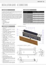
INSTALLATION GUIDE - KZ CONVECTORS 2. CONTENTS OF THE BOX 1. UNIT DESCRIPTION It is a built-in convector with a removable design front panel. The KZ-series units are available with 2 installation depths. The design front panel of the convector is available as oak (natural) or stainless steel. The convector body is to be fully built in the partition wall. The horizontal and vertical position is adjusted using anchoring holes in the stainless steel body. There are holes prepared in the side, bottom and, as the case may be, back of the convector body for heating water connection. The convectors are supplied with left-hand or right-hand connection according to the customer specification which must be provided when ordering. According to the customer requirement, the convector is supplied either with wooden or stainless steel front panel. Benefits of convectors with fan: Heat exchanger Hose ½´´ - 65 mm (bellows hose) Control screw fitting - straight ½´´ 7. EB CONTROL UNIT – fan motor control unit 8. TERMINAL BOARD – for connecting the electric valve cable (KZ 91 only) 9. CABLE GROMMET – intended for the control unit power supply cable 10. TEMPERATURE SENSOR – for sensing water temperature 11. RUBBER ANTI-VIBRATION RING – for flexible mounting of the fan module. To reduce vibrations. 12. BALL VALVE – used to shut off the heating circuit Use: dry environment Maximum operating pressure: 1 MPa. Maximum operating temperature: 90 °C. Operating medium: water. The use of other media is prohibited. Water may not be mixed with other substances. Environment: interiors with temperatures ranging between +5 °C and +40 °C. Power supply: 12V AC from a suitable transformer for the given environment and convector fan types (DC) *According to the customer’s request, the convector may be equipped with a wooden or stainless steel panel. 6. CROSSBAR – crossbar for installation Control screw fitting - angular ½´´ 5. DIRECTIONAL METAL PLATE – for directing the air flow 17. SCREW ANCHOR – for fixing the screw in the wall. 4. FAN – used for forced convection 16. SCREW – for mounting of the bearing part of the convector. Ball valve - straight ½´´ 3. HEAT EXCHANGER – copper pipes with pressed-on aluminum fins through which the heating water flows (KZ91 - 4 pipes, KZ60 - 2 pipes). 15. GASKET – seals joints between valves, hoses, and exchangers (KLINGERSIL C4400). MINIB, a.s. recommends this sealing as the optimal sealing solution because other materials (rubber, NBR, silicon) do not provide the required sealing characteristics. 2. FRONT PANEL OF THE CONVECTOR – a design piece (wood / stainless steel) 14. HOSE – the bellows hose is a stainless hose intended for fitting connection to the convector exchanger. Front panel (wood or stainless steel) 1. CONVECTOR BODY – bearing structure of the convector parts 13. CONTROL SCREW FITTING – a valve that controls/ adjusts heating water flow. Connection From the side Convector body Hose ½´´ - 42 mm (bellows hose) High output Silent operation Low hot water consumption Very short response time Design Minimum requirements for operation and maintenance
Open the catalog to page 1
4. INSTALLATION AND MOUNTING OF THE UNIT KZ convector can be connected to water supply from the side, from the back and, if applicable, from the bottom of the convector body. Flexibility of connection in different directions is provided by 2 flexible hoses (bellows hoses). See the Table – Contents of the box. Air vent valve Water supply pipe Return pipe Please read the installation instructions before you start. Fix the unit using the screws and anchors included in the accessories. Before installation in the wall it is necessary to know whether there will be empty space between the convector...
Open the catalog to page 2All MINIB catalogs and technical brochures
 NCA 4P
2 Pages
 NCA
NCA2 Pages
 NKB
NKB2 Pages
 NPB
NPB2 Pages
 SKB
SKB2 Pages
 SPB
SPB2 Pages
 INNOVATIVE ACTIVE CHILLED BEAM
12 Pages
 NEWS
NEWS28 Pages
 THE BESTSELLING CONvECTORS
52 Pages
 IG - FLOOR CONVECTORS TE
4 Pages
 IG - DP CONVECTORS
2 Pages
 IG - SK CONVECTORS
2 Pages
 FLOOR CONVECTORS with fan
47 Pages
 CONTROL ACCESSORIES
24 Pages
 CONTTROLS
3 Pages
 WALL-MOUNTED AND FREE-STANDING
40 Pages
 FLOOR CONVECTORS
72 Pages
 WALL FREE CONVECTORS
36 Pages
 NEWS MINIB
3 Pages
 DESIGN CONVECTORS
12 Pages
 BEST OF MINIB
11 Pages
 CATALOGUE MINIB
108 Pages
 COIL – PT300
1 Page


Archived catalogs
 COIL – PT80
1 Page
 COIL – KT
2 Pages
 COIL – PO
1 Page
 COIL – P
1 Page
 COIL – PT
1 Page
 COIL – KO
2 Pages
 COIL – KTO
2 Pages
 COIL – T 60
2 Pages
 COIL – SW420
1 Page
 COIL-T50
2 Pages
 COIL – PT180
1 Page
 COIL – NW340
1 Page
 COIL – PMW165
1 Page
 COIL – NW170
1 Page
 COIL – PT105
1 Page
 COIL – T80
2 Pages
 COIL – KT1
2 Pages
 COIL – KT2
2 Pages
 COIL-KT3 105
2 Pages
 COIL – HCM
2 Pages
 COIL – MT
2 Pages
 COIL – HC4pipe
2 Pages
 COIL – PMW205
1 Page
 COIL – M0
2 Pages
 COIL – HCM4pipe
2 Pages
 COIL – KT3
2 Pages
 COIL – MT2
2 Pages
 COIL – NK1
2 Pages
 COIL – NU2
1 Page
 COIL – LP
1 Page
 COIL – SK PTG - NK PTG
1 Page
 COIL – NP2/4
1 Page
 COIL – PMW90
1 Page
 COIL – KT110
2 Pages
 COIL – SP1/4
1 Page
 COIL - SW250
1 Page
 COIL – PW
1 Page
 COIL – TE
1 Page
 COIL – NU1
1 Page
 COIL – SU1
1 Page
 COIL – KP
1 Page
 COIL – NP1/4
1 Page
 COIL – HC
2 Pages
 COIL – SK2
2 Pages
 COIL – SK1
2 Pages
 COIL – DP
1 Page
 COIL – SU2
1 Page
 COIL- SP2/4
1 Page
 COIL – PMW125
1 Page
 Minib TH-0343 Termostat
1 Page
 Minib TH-0108 Termostat
88 Pages
 MINIB 2009
88 Pages

- Metal convector
- Contemporary convector
- Horizontal convector
- Electric convector
- Rectangular convector
- Wall-mounted convector
- White convector
- Linear convector
- Floor convector
- Convector with ventilator
- Chilled beam
- Heating and cooling convector
- Free-standing convector
- Active chilled beam
- Stainless steel convector
- Fanless convector