- Products
- Catalogs
- News & Trends
- Exhibitions
Mills Tour
1 /28Pages

Mills Tour
1 /28Pages
Catalog excerpts

MILLS TOUR Shoring tower for civil engineering and public works Mills scaffolding solutions
Open the catalog to page 1
MILLS TOUR Mills Tour: shoring tower for civil engineering works he MillsTour shoring system can be used to erect selfsupporting shoring towers, in runs or blocks, to transmit vertical loads to the ground. For many years, Mills Tour has been the French market leader for civil engineering and public works. This high performance shoring system has a telescopic level, modular units and lightweight components. TABLE OF CONTENTS Presentation Assembly Tower configuration Specifications and load capacity Particular applications Components Recommendations Mills is certified to use the mark for the “Mills...
Open the catalog to page 2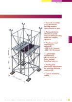
MILLS TOUR > General assembly using automatic locking without special tools or pins. > Maximum load capacity per standard: - MT 65: 6.5 tonnes - MT 100: 10 tonnes > Lightweight components (9.4 kg max) to limit manual handling injuries. > Moving and telescopic adjustment for re-using without reassembly. 1.00 MILLS TOUR > Runs and blocks of towers can be erected without using tube and coupler systems.
Open the catalog to page 3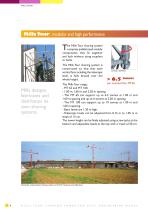
MILLS TOUR Mills Tour: modular and high performance he Mills Tour shoring system comprises prefabricated modular components that fit together and lock without using couplers or bolts. The Mills Tour shoring system is constructed so that that each vertical face, including the telescopic level, is fully braced over the whole height. Mills designs, fabricates and distributes its own shoring systems. per standard for MT65 The Mills Tour range: - MT 65 and MT 100. - 1.00 m, 1.60 m and 2.20 m spacing. - The MT 65 can support up to 6.5 tonnes at 1.00 m and 1.60 m spacing and up to 6 tonnes at 2.20 m...
Open the catalog to page 4
MILLS TOUR MILLS TOUR Adjustable head Access deck Scaffold plank MT ladder Telescopic standard and locking pin Telescopic frame and pin Fixed height standard Fixed height frame Horizontal diagonal brace Base ledger Screw jack
Open the catalog to page 5
MILLS TOUR Assembling and dismantling ASSEMBLY REQUIREMENTS > Check the ground load distribution. > Ensure that the base is level. > Ensure that the tower is stable. > Dismantle in the reverse order of assembly. > Check that the jacks are vertical. > 1 - Erect the base and level it. > 2 - Fit the standards and the first level frames. > 3 - Fit the standards and frames of the following levels from the lower level. > 4 - Fit the ladder and 2 scaffold planks. > 5 - Move up to the next level and fit 2 more scaffold planks. > 6 - From the full deck, fit the standards and frames for the next level....
Open the catalog to page 6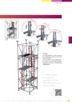
MILLS TOUR MILLS TOUR The scaffold planks are used as decking for assembling the towers or for access for the personnel. There are 29.5 cm wide scaffold planks for 1.00 m, 1.60 m and 2.20 m spacing. The maximum load for a scaffold plank is 200 kg/m2. A video of the erection is available on the CD-ROM and on www.mills.fr. Use this QR code to view the presentation and erection video from your telephone.
Open the catalog to page 7
MILLS TOUR Composition and height of towers > Bill of materials of towers: 1.60 m x 1.60 m tower MT65 The heights shown were calculated using T1 screw jacks and adjustable heads. Height above ground at base of head Component Extra fixed level Extra telescopic level Fixed height frame Fixed height standard Telescopic standard Base ledger Telescopic frame Horizontal diagonal brace Access deck Access ladder Scaffold plank NB: The base ledgers and frames are the same for the MT 65 and the MT 100 shoring towers but the standards for MT 100 towers are 1.6 cm further apart than standards for MT 65 towers....
Open the catalog to page 8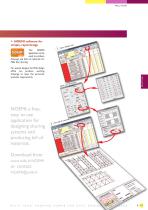
MILLS TOUR > NOEMI software for simple, rapid design The NOEMI application can be used to produce drawings and bills of materials for Mills Tour shoring. 1 2 3 4 5 17 8 90000000000 0 0 For special designs, the Mills design office can produce working drawings to meet the particular worksite requirements. yo u r d Select NOEMI: a free, easy to use application for designing shoring systems and producing bill of materials. MILLS TOUR Download from
Open the catalog to page 9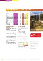
MILLS TOUR Specifications and load capacity > Specifications of the main components: Standard MT65 fixed height standard Tube Ø60.3x3.2 MT65 telescopic standard Tube Ø48.3x6.0 MT100 fixed height standard Tube Ø76.1x4.5 MT100 telescopic standard Tube Ø60.3x6.3 Frame Ledger and upright Tube 30x30x2 Diagonal brace Tube Ø26.9x2 Base ledger Tube 50x30x2 Adjustable heads and screw jacks MT65 screw Ø33 studding MT100 screw Ø40 studding > Maximum load on standards The maximum load on each standard is: - MT65 at 1.00 and 1.60 m spacing: 6.5 t - MT65 at 2.20 m spacing: 6t - MT100 at 1.00 and 1.60 m spacing:...
Open the catalog to page 10
Fixed base plate: MILLS TOUR Adjustment from 15 to 105 15 cm steps Telescopic level Fixed height level MILLS TOUR
Open the catalog to page 11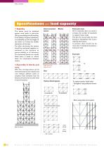
MILLS TOUR Specifications and load capacity The tower must be stabilised against wind loads, in particular during assembling and dismantling. In the absence of special calculations, it is advisable to limit the height of the tower to 4 times the smaller dimension of the base. For taller structures, the towers should be connected together or anchored to the structure to ensure stability in all directions. The horizontal braces are usually fitted every 4 levels or where there are connections between towers. > Assembly in blocks and runs Mills Tour shoring towers can be interconnected to form blocks...
Open the catalog to page 12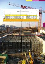
MILLS TOUR Mills Pano Mills Tour MILLS TOUR Roof over SNCF railway tracks, Batignolles, Paris
Open the catalog to page 13
MILLS TOUR Special features > Adjusting the telescopic standards Telescopic standard height adjustment Telescopic standard > Using the end-to-end connector (MT 65 only). Using the end-to-end connector for erection on a slope. Ø 49 tube brace with couplers Ø 49 tube with couplers Fixed height standard End-to-end connector Adjustable coupler 49/60 Horizontal bearing level End-to-end connector Telescopic standard with locking pin Adjustable coupler 49/49 T2 adjustable head T2 base plate All dimensions are in cm unless otherwise stated.
Open the catalog to page 14All MILLS catalogs and technical brochures
 HEAVY-DUTY WALL BRACKET
1 Page
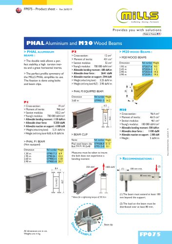 FP075
FP0751 Page
 ESCALIB Mills MDs*
24 Pages
 ESCALIB MILLS KIT
20 Pages
 TIROIR
8 Pages
 Escalib Mills
16 Pages
 Tourechaf
32 Pages
- Stairs
- Staircase without risers
- Metal staircase
- Straight stairs
- Metal frame staircase
- Design software
- Metal step staircase
- 3D software
- Industrial formwork
- Beam
- Precast staircase
- Beam with symmetrical section
- Modular formwork element
- Steel structure software
- 2D software
- Metal formwork
- Industrial calculation software
- Outdoor staircase
- Metal scaffolding