Catalog excerpts
VERIFICATION SUMMARY GEOTECHNICAL SOLUTION
Open the catalog to page 1
About MIDAS A LEADING GLOBAL Engineering Solutions Provider Headquarters Branch Offices Sales Offices Saint Petersburg Russia Lithuania Netherlands Italy Czech Slovenia Greece China (Beijing) Algeria Mexico Puerto Rico India (Mumbai) Taiwan Philippines KOZO KEIKAKU ENGINEERING ITOCHU Techno-Solutions JIP Techno Science Chennai Malaysia Nigeria Port Harcourt Venezuela Colombia Ecuador Japan (Tokyo) Cybernet Systems Tanzania Bolivia Being the largest developer of structural and geotechnical engineering software with extensive research in leading technologies in the world, MIDAS has garnered...
Open the catalog to page 2
About SoilWorks Geotechnical Solutions For Practical Design SoilWorks Concept Soft Ground Geotechnical analysis software programs available today generally handle specific types of geotechnical problems with varying degrees of limitations in functionality. SoilWorks is designed to handle any geotechnical problems encountered in the practice of soil / rock mechanics. SoilWorks is designed for structural engineers with a background in geotechnical engineering and geotechnical engineers with a background in finite elements. SoilWorks Development Motive In the practice of geotechnical design,...
Open the catalog to page 3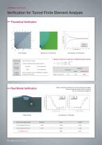
Verification for Tunnel Finite Element Analysis Theoretical Verification [Unit Model] Radius of yield zone: Salencon (1969) theoretical method Analysis Type Element Boundary Condition Loading Condition Static Nonlinear Analysis 4-Node Quadrilateral Plain Stress Element Left Side X-Dir. Restrained Y-Dir. Restrained Initial compressive stress of 300MPa is applied to the right and top sides SoilWorks Theoretical Value Radius of yield zone Static nonlinear analysis for tunnel construction stages Ground material model: Mohr-Coulomb No. of construction stages: 8 Real Model Verification...
Open the catalog to page 4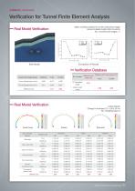
Verification for Tunnel Finite Element Analysis Static nonlinear analysis for tunnel construction stages Ground material model: Mohr-Coulomb No. of construction stages: 11 Real Model Verification Construction stage Construction stage [Real Model] Verification Database No. of cases Difference with Difference with other program (%) theory (%) FLAC PLAXIS Construction Stage Results 8 Real model cases Real Model Verification Lining analysis Change in thickness: 0.3 - 0.5m, B=1m No. of loading types: 6 [Axial force] Non-prismatic Section Program used Axial force Beam load (Horiz) Point load...
Open the catalog to page 5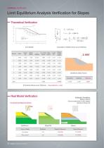
Limit Equilibrium Analysis Verification for Slopes Theoretical Verification [Unit Model] [Calculation of Safety Factor as per Fellenius] W × Sin(a) Shear Length (m) (kN/m) (kN/m2) [Theoretical Values as per Fellenius] [SoilWorks Safety Factor] Real Model Verification Verification Conditions Bishop method Ground water level in rainy season Number of slices: 30 Unreinforced Slope (Cut Zone) Slope/W (Difference) Talren (Difference) Rainy season SoilWorks_Verification Summary
Open the catalog to page 6
Limit Equilibrium Analysis Verification for Slopes Verification Conditions Bishop method Ground water level in rainy season Number of slices: 100 Real Model Verification Soil Nail Reinforced Slope [SoilWorks] [Rainy Season] [Rainy Season] Rainy season Verification Conditions Bishop method Ground water level in rainy season Number of slices: 100 [Talren] Earth Anchor Reinforced Slope [SoilWorks] [Rainy Season] [Rainy Season] Rainy season Database of Verifications Difference in Safety Factors with Other Programs based on the average of absolute differences for all the cases Difference with...
Open the catalog to page 7
Finite Element Analysis Verification for Slopes — Strength Reduction Method * Overview of Analysis [Zienkiewicz, 1975] * Factor of Safety (FS) & Strength Reduction Factor (SRF)
Open the catalog to page 8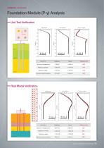
Foundation Module (P-y) Analysis Unit Test Verification Moinent(lbs in) Shear Force(lbs) Geotechnical Solution for Practical Design 08
Open the catalog to page 9
1-D Consolidation Analysis Verification for Soft Ground Theoretical Verification Traffic loads Fill embankment (above water level) Classification Hand calculation Fill embankment (below water level) Over-consolidated clay Total Settlement Consolidation Period (cm) (days) U=90% Real Model Verification SoilWorks Check Location Time - Settlement Time - Difference Settlement difference Max difference: 0.19cm / Max convergence error: 0.07cm Time(day) Settlement difference Max difference: 0.57cm / Max convergence error: -0.14cm SoilWorks_Verification Summary 2-D consolidation settlement (cm) 1-D...
Open the catalog to page 10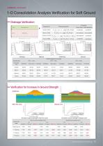
1 -D Consolidation Analysis Verification for Soft Ground Drainage Verification Weak layer Time (days) Geotechnical Solution for Practical Design 10
Open the catalog to page 11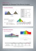
Verification for Seepage Finite Element Analysis Theoretical Verification Analysis Type 2D Plane Element (Steady Flow) Analysis Model 3-Node triangle element Permeability coefficient Water level at dam left [Unit Model] Total water head 1 m Other nodes Boundary Condition [Theoretical Solution] Boundary Condition: AC face – constant pressure water head (= constant) AB face: No normal flow, qv =0 CB face: Seepage h=y Total Flux: Line AB: n=s & qn = qs , qv = 0 Line CD: qx = k/2, Total fluxQx= k/2 x L Line AC: qn = k x s/2L, Total flux Qx = k/2 x L Line BC: qs = k x n/2L, Total flux Qx = k/2 x...
Open the catalog to page 12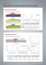
Verification for Seepage Finite Element Analysis Real Model Verification Pressure Head(m) Transient Flow Seepage Analysis - Saturated Soil [Real Model] [Water Level Drop Function] [Pressure Water Head Results] Unit: m [Seep/W – Pressure Water Head at 14400sec] SoilWorks Min. Max. Total water 14.970 head Pressure water head -5.311 [SoilWorks – Pressure Water Head at 14400sec] [Water Head Results at Water Level Drop] Real Model Verification Transient Flow Seepage Analysis - Saturated Soil [Real Model] Pressure Head(P) Permeability coefficient ratio Pressure Head(P) Pressure Head Permeability...
Open the catalog to page 13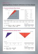
Limit Equilibrium Analysis Verification for Rock Slopes Theoretical Verification [Plane Failure] y [Unit Model] [Input Data] Height(H) Slope Dip(α) Sesimic Coeff.(sc) Unit Weight(γr) Unit Weight(γw) Water Percent(%) Cohesion(c) Friction Angle(θ) [Theoretical Equation] Theoretical Verification [Wedge Failure] [Unit Model] SoilWorks_Verification Summary [Theoretical Equation]
Open the catalog to page 14All MIDASIT catalogs and technical brochures
-
midas FEA
7 Pages
-
GTS NX
16 Pages
-
midas GTS
5 Pages
-
midas Civil
12 Pages
-
SoilWorks 2013 (V2.1)
13 Pages
-
FX+ Modeler
49 Pages
-
Midas Design+
6 Pages
-
midas GTS Description PPT
118 Pages
-
SoilWorks Description PPT
83 Pages
-
midas FX+ for DIANA
41 Pages
-
midas Civil - Description PPT
51 Pages
-
MIDAS IT - Description PPT
93 Pages
-
NFX description
65 Pages
-
NFX catalog
28 Pages
-
SoilWorks Catalog
26 Pages
-
SoilWorks Verification Summary
16 Pages
-
SoilWorks 2013 v1.1 Description
83 Pages
-
Midas GTS 2010 catalog
36 Pages
-
DShop catalog
5 Pages
-
FXP Modeler 2012
49 Pages
-
FEA description
78 Pages
-
Midas Civil catalog
28 Pages
-
midas IT
24 Pages
-
midas gen
24 Pages
-
midas FEA
24 Pages
-
MIDAS/SET
6 Pages
-
MIDAS/GEN
16 Pages
-
MIDAS/FX+
11 Pages
Archived catalogs
-
midas civil
26 Pages


