Catalog excerpts

Bridging Your Innovations to Realities
Open the catalog to page 1
Graphic User Interface Graphic User Interface 02 Modeling Features 07 Bridge Applications 13 Segmental Bridges 17 Cable Bridges 28 Analysis Features 34 Result Evaluation 43 Design Features 48 2
Open the catalog to page 2
User Interface Organization of Windows and Menu System Menus and Windows Layout Bridging Your Innovations to Realities Main menu Works Tree Command Line Mode* ia»d arwtfSK fieaiti rjwyi Mode Query look fflndo* tJ* we*d Node Bamert Property BC/Maw SUQ9 [Load Movrtj Setttem. fleaJt Influarr... Querv Tabbed Toolbar - Analysis Conbgl Data Context menu Task Pane Render View Message Window Unit Control - Tabbed toolbar is designed to minimize mouse motion for efficiency. - Excel compatible tables for both input and output. - Works Tree enables to manipulate entered data more easily and avoid...
Open the catalog to page 3
User Interface View Control Bridging Your Innovations to Realities Various model display methods Wire Frame Hidden / Perspective Remove Hidden line Transparency Advantages - The Render View function assist the user to accurately grasp the 3D views of the model and the analysis and design results through diverse view angles and points. - These functions help the user grasp the input state of the model and manipulate the model as much as desired. - It minimizes possible data input errors and differentiate design reports by extensive visualization functions.
Open the catalog to page 4
User Interface I Visualization Options Bridging Your Innovations to Realities Controls visualization options for Elements / Load / Boundary Condition - It provides graphical representation of all types of data entries such as node/element numbers, material properties, section names, loadings, support conditions, end release conditions, rigid body connection conditions, design parameters, etc. - These representation capabilities enable the user to verify the status of data entries by graphics in the working
Open the catalog to page 5
User Interface Merge Data Files Bridging Your Innovations to Realities 3 separate data files merged into one total model Support Frame Vessel 1 Vessel 2&3 Advantages - It enables to divide the modeling task of a complex structure where the geometric configuration is irregular, complicated and large, - User can combine several sub-models where the geometric shapes are modeled separately for the final structural analysis model.
Open the catalog to page 6
Modeling Features Graphic User Interface 02 Modeling Features 07 Bridge Applications 13 Segmental Bridges 17 Cable Bridges 28 Analysis Features 34 Result Evaluation 43 Design Features 48 7
Open the catalog to page 7
Modeling Features Post-tensioned Box Section Numerous built-in section types Advantages - It enables to create typical PSC bridge section by specifying few section characteristics . - PSC section wizard improves productivity of your modeling tasks. Bridging Your Innovations to Realities
Open the catalog to page 8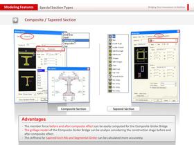
Modeling Features Special Section Types Bridging Your Innovations to Realities Composite / Tapered Section Section Data Composite Section ^jjjp Double Angle (_) Solid Octagon Solid Track Tapered Section The member force before and after composite effect can be easily computed for the Composite Girder Bridge The grillage model of the Composite Girder Bridge can be analyze considering the construction stage before and after composite effect. The stiffness for tapered Arch Rib and Segmental Girder can be calculated more accurately.
Open the catalog to page 9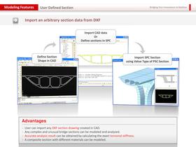
Modeling Features User Defined Section Bridging Your Innovations to Realities Import an arbitrary section data from DXF Import CAD data Or Define sections in SPC Define Section Shape in CAD Import SPC Section using Value Type of PSC Section Advantages - User can import any DXF section drawing created in CAD. Any complex and unusual bridge sections can be modeled and analyzed. Accurate analysis result can be obtained by calculating the exact torsional stiffness. A composite section with different materials can be modeled.
Open the catalog to page 10
Modeling Features Material Definition Bridging Your Innovations to Realities Provides two types of Time Dependent Materials (Creep & Shrinkage / Comp. Strength) Add/Modify Time Dependent Material (Creep / Shrinkage) AaWModityTime Dependent Material (CDmp. Slrenglh) Characteristic compressive strength of concrete Relative Humiditv of amtaent environment (40 - 99): h - 2 * Ac / u (Ac : Section Area, u I Penmeter n contact with atmosphere) r Rapid hardenng h>gh strength cement (RS) (• Normal or rapid hardenng cement (N, R) r Slowly hardenng cement (SI) Aoe of concrete at the bwjjnrtnq of...
Open the catalog to page 11
Modeling Features |WM|jj|lUj Vehicular Loads Available Vehicular Load Codes Bridging Your Innovations to Realities • AASHTO LRFD • AASHTO Standard • Caltrans Standard • PENNDOT LRFD •User Defined Define Standard Vehicular Load VehraJar Load Property Vehcutor Load TVDB : aojQi: Tandem system,o> Dynamo amplification factor nduded Lane Numbed Remaining Area ui Factor for Tandem System ; Tandem System UDL System Adjustment Me Loads Adjustment Uniformly Dist Factor (kN) Factor Loads (kNftrr') Influence line and influence surface analysis - It applies vehicle loads considering all possible...
Open the catalog to page 12
Bridge Applications Graphic User Interface 02 Modeling Features 07 Bridge Applications 13 Segmental Bridges 17 Cable Bridges 28 Analysis Features 34 Result Evaluation 43 Design Features 48 13
Open the catalog to page 13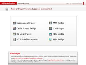
Bridge Applications Bridges Wizards Bridging Your Innovations to Realities Types of Bridge Structures Supported by midas Civil Suspension Bridge rj MSS Bridge ±\ Cable Stayed Bridge E| ILM Bridge £H| RC Slab Bridge £| FCM Bridge ml RC Frame/Box Culvert [§= FSM Bridge It provides Bridge Wizards for modeling various types of bridge construction encountered in practice. The wizards can quickly create the models of completed structures. Since the wizards incorporates bridge engineering knowledge, it significantly reduces time on model generation including automatic construction stage definition.
Open the catalog to page 14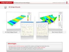
Bridge Applications Reinforced Concrete Bridges Bridging Your Innovations to Realities RCSlab Bridge Wizard - Auto-generation of entire process required for analysis and design by simple data entry - Auto-generation of loads and combinations based on various design standards - Design of reinforcing bars and strength verification of beams and columns
Open the catalog to page 15All MIDASIT catalogs and technical brochures
-
midas FEA
7 Pages
-
GTS NX
16 Pages
-
midas GTS
5 Pages
-
midas Civil
12 Pages
-
SoilWorks 2013 (V2.1)
13 Pages
-
SoilWorks VERIFICATION SUMMARY
24 Pages
-
FX+ Modeler
49 Pages
-
Midas Design+
6 Pages
-
midas GTS Description PPT
118 Pages
-
SoilWorks Description PPT
83 Pages
-
midas FX+ for DIANA
41 Pages
-
MIDAS IT - Description PPT
93 Pages
-
NFX description
65 Pages
-
NFX catalog
28 Pages
-
SoilWorks Catalog
26 Pages
-
SoilWorks Verification Summary
16 Pages
-
SoilWorks 2013 v1.1 Description
83 Pages
-
Midas GTS 2010 catalog
36 Pages
-
DShop catalog
5 Pages
-
FXP Modeler 2012
49 Pages
-
FEA description
78 Pages
-
Midas Civil catalog
28 Pages
-
midas IT
24 Pages
-
midas gen
24 Pages
-
midas FEA
24 Pages
-
MIDAS/SET
6 Pages
-
MIDAS/GEN
16 Pages
-
MIDAS/FX+
11 Pages
Archived catalogs
-
midas civil
26 Pages


