Catalog excerpts

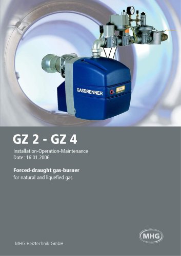
Forced-draught gas-burner
Open the catalog to page 1
Safety instructions - Please observe! Please comply with the assembly, operation and maintenance instructions (or installing and adjust- In Switzerland, the guidelines issued by PROCAL and those of the Vereinigung Kantonaler Feuerver- sicherungen. VKF (Association of Canton Fire Insurances) must be observed. In particular the fire guidelines "Thermal Heating Systems". Please read this installation manually carefully before starting installation. We cannot assume any liability or guarantee for damage caused by failure to comply with this Installation manual! Work which is not tarried out...
Open the catalog to page 3
The following standards and regulations are to be observed during Installation and operation of the burner. Heating system ordinance Firing ordinance of the German federal states First ordinance for implementation of the German Emission Pro- Guidelines for preven I nq d.¡m.'¡ge 'ru-r corrosion and scale formation in hot water heating installations Regulations and special requirements issued by the energy util- Heating boilers with forced draft burners Calculating the dimensions of chimneys Hot water heating installations - safety requirements Oil firing installations - construction,...
Open the catalog to page 4
The adjacent diagram cesie:; die a op'ox i m ate performance range of ihe different burner sizes as a function of the resis- tance measured a: Po ooi c's gas exit du' ng operation "he ; mves vovï maxim JIT va !J(?% -I 'd i tr-eipond vv :li t"e mede I -e starling 'esistane? cy the ooi c is of dee ; ve importance to die attaraole burner performance. Two-stage Operation The use of a modern, symmetrically designed high-ocrormance fixing sys'.err i" con june l on w :h orecisely lunc'.ioning adjust- ramps assembly (GZ 3.1 -GZ 4; make:, it oossiole to adjust out- put precisely to heat -a rea...
Open the catalog to page 5
Easy Installation The burner comes concilo:-", ine ..cl ng power dependent equipment, and every component is clearly designed so that a qualified heating engineer will have no problems with Installa- tion, starting, and servicing. 5ci ewi ant; gaske". ftr "ho burner instai -it on are i"ciuced The burner is electrically connected by a 7-pole plug according to The burners are pre-tested and pre-set. The burner performance is changed by adjusting ihe gas-flow 'hrottle and the settings [dimension B and air damper position). In Germany, the he.iting engineer -las 10 consider the existing...
Open the catalog to page 6
GZ 2 - GZ 4 / 100 - 1450 kW Installation-Operation-Maintenance Rating of the gas ramps Depending on the available gas flow pressure, a correspondingly rated gas compact ramps or gas ramp system will be installed in the factory. If the minimum connection pressure is not achieved under rated heat load, a gas ramp system will have to be used with a larger rated width; the gas pressure must be increased at the utility company's gas transfer point, or the cross section of the supply line between the gas transfer point and the gas ramp system must be enlarged. Before the gas fan burner starts up...
Open the catalog to page 7
Burner and gas ramps taken from the table on page 9 form a complete unit which has been subject to model certification. • Dirt pan with sieve and filter mat • Safety solenoid, opens and shuts quickly, with setting for gas ■ Solenoid with selling tor starting volume and gas volume stage 1 , opens slowly and shuts quickly • Pressure controller with admission pressure compensation • Pressure detector, setting range 2.5 - SO mbar • Electrical connection with plug Burner and gas ramps taken from the table on page 9 form a complete unit which has been subject to model certification. • Dirt pan...
Open the catalog to page 8
Every burner is pre-tested and pre-set. The basic adjustment is shown in the table a neve ¡reVente vak.es valid for the gas type indicated). I he turner must oc- adjusted and started by a qualified heating ■ gas pressure (nozzle pressure): at the adjusting screw of the • q,is volume slaqe 'I ■ -A die adjustment for vjlve Q • q,is voLrie slage 1 ■ al I'M; ,it¡|iisl nq vv'.:el & i..: ciioiu stac: • for gas rarnp systems DN 65/80/ 100 at the motor valve S> (Johnson Controls see illustration on the left) • starting gas volume - at the adjusting screw of valve 1 ® '—opening quickly opening...
Open the catalog to page 10
GZ 2 - GZ 4 / 100 - 1450 kW Position air guidance device GZ 3 and GZ 4 Installation-Operation-Maintenance Air inlet nozzle Fig. 10: Adjusting the air inlet nozzle for GZ 2 / GZ 3 The air inlet nozzle can be adjusted once the burner has been opened. Both screws on the air inlet nozzle should be loosened slightly, and must be screwed tight again after the adjustment has been made. Fig. 9: Fig. 11: Adjusting the air inlet nozzle for GZ 4 The air inlet nozzle can be adjusted once the burner has been switched off and the suction silencer has been hinged away. Both screws of the air inlet nozzle...
Open the catalog to page 11
Installation-Operation-Maintenance Settings GZ 2 - GZ 4 / 100 - 1450 kW Spark electrode setting GZ 2 GZ 3 GZ 4 natural gas GZ 4 liquefied gas Fig. 13: Installation position Multiblock All gas Multiblocks must only be installed as shown below Installation in the grey area is not permitted. Fig. 12: Fig. 14: 12
Open the catalog to page 12
Installation-Operation-Maintenance GZ 2 - GZ 4 / 100 - 1450 kW Fault diagnosis Fault diagnosis MMI 810 Flame monitoring makes use of the conductivity and rectifier effect of the flame, by means of an ionisation electrode. The flame signal amplifier only reacts to the DC component of the flame signal. Fault Burner does not start, program display remains the same • Faulty electric lead Burner does not start, program display turns constantly • Air pressure switch not in idle position (working contact must be open) A short circuit between ionisation electrode and earth causes a fault cutout....
Open the catalog to page 13
Installation-Operation-Maintenance Fault diagnosis TMG 740-3 and TMG 740-2 Fault Remedy Burner does not start, program display remains the same • Faulty electric lead Burner does not start, program display turns constantly • Air pressure switch defect or not in idle position (working contact must be open) • Thermostat or gas switch "OFF"" Automatic unit shows a • Air pressure switch contact does fault just after starting not close pre-venting (line in • Flame signal blue box) Automatic unit shows a • Air pressure switch contact fault during preopens venting (blue area) • Flame signal...
Open the catalog to page 14All MHG Heating catalogs and technical brochures
-
Alucon
2 Pages
-
Alubox 50-2200kW
2 Pages
-
SuperBOX 160-4,200kW
2 Pages
-
Ultrabox 170-1330kW
2 Pages
-
MHG Brochure
12 Pages

